Assembly instructions – GAMMA 5800 Els STRINGING MACHINE 2 POINT SC MOUNTING (Issue 6 - July 2014) User Manual
Page 5
5
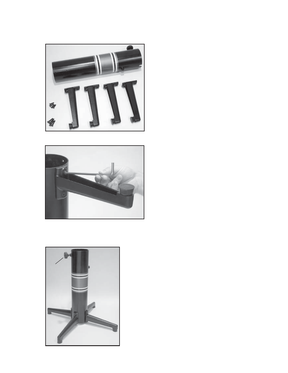
Floor Stand Leg Assembly
The stringing machine uses a four leg Floor
Stand design. The legs must be assembled
to the Lower Column before use. Remove all
parts from the shipping carton to conf rm that
contents match the list of parts on Page 4.
Floor Stand Leg Assembly (Cont.)
Align the holes in the leg f ange with the
matching holes in the Lower Column. Se-
cure the leg with one M8 FLAT HEAD screw
through the upper hole, and one M8 SOCKET
HEAD cap screw through the bottom hole.
Install one 8mm nut on each screw. Repeat
this procedure for the three remaining legs.
ASSEMBLY INSTRUCTIONS
Floor Stand Leg Assembly (Cont.)
To complete the Floor Stand, screw the height adjustment
locking knob (“A”) into the side of the Lower Column.
The locking knob should not protrude beyond the inside
of the Lower Column at this time.
“A”
- 8800 Els STRINGING MACHINE 2 POINT SC MOUNTING (Issue 6 - July 2014) 8800 Els STRINGING MACHINE 6 POINT SC MOUNTING (Issue 9 - July 2014) 5800 Els STRINGING MACHINE 2 POINT SC MOUNTING (Issue 5B - March 2014) 5800 Els STRINGING MACHINE 6 POINT SC MOUNTING (Issue 5B - March 2014) 5800 Els STRINGING MACHINE 6 POINT SC MOUNTING (Issue 7 - June 2014) 5800 Els STRINGING MACHINE 6 POINT SC MOUNTING (Issue 6 - June 2014) 8800 Els STRINGING MACHINE 2 POINT SC MOUNTING (Issue 5B - March 2014) 5800 Els STRINGING MACHINE 6 POINT SC MOUNTING (Issue 6B - March 2014) 8800 Els STRINGING MACHINE 6 POINT SC MOUNTING (Issue 8B - March 2014)