External accessory components – GAI-Tronics MI05-101 Merge / Isolate Cabinet with External Option User Manual
Page 12
Pub. MI05-101iom.2
Model MI05-101 Merge/Isolate Cabinet
Page: 12 of 24
\\86h27g1-fs\iomdocs\opnotes -- released\mi05-00x merge-isolate cabs\mi05-101.dir\mi05-101iom2.doc
01/09
External Accessory Components
The following components are installed externally to the Model MI05-101 Merge/Isolate Cabinet. All
cable required for installation of this equipment must be provided by the installer.
Model 10959-101 Audio Messenger Interface
CAUTION
The AMI is supplied with an external plug-in power supply adapter, and it
should not be used in this application.
I
ns
t
e
a
d,
c
onne
c
t
t
he
AMI
’
s
i
nput
powe
r
t
e
r
mi
na
l
s
t
o
t
he
24
V
dc
output power terminals provided on the M/I
ca
bi
net
’
s
t
e
r
mi
na
t
i
on
pa
ne
l
pe
r
t
he
t
a
bl
e
be
l
ow.
1. Mount the AMI in accordance with Pub. 42004-398, which is packaged with the equipment.
2. Re
pr
ogr
a
m
t
he
AMI
a
s
de
s
c
r
i
be
d
i
n
t
he
“
Pr
ogr
a
mmi
ng
t
he
AMI
”
s
e
c
t
i
on
be
l
ow.
Se
ve
r
a
l
pa
r
a
me
t
e
r
s
mus
t
be
c
ha
nge
d
f
r
om
t
he
AMI
’
s
f
a
c
t
or
y
de
f
a
ul
t
pr
ogr
a
mmi
ngto allow proper operation with the
Model MI05-101 Merge/Isolate Cabinet.
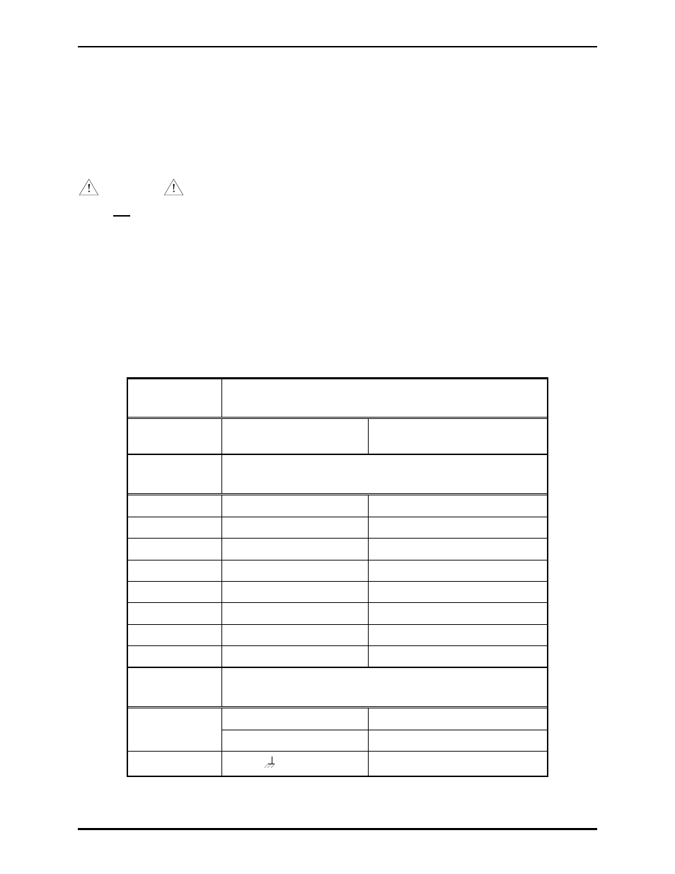
3. Connect the AMI to the External Interface PCBA as follows using a 5-pair, No. 18–22 AWG cable
for audio and alarm inputs and a 3-conductor cable for dc power. Refer to the following table for all
connections between the AMI and the M/I cabinet:
Function
AMI Page/Party
®
Interface PCBA
Connect
to
Merge/Isolate External
Interface PCBA
Page Line
TB1-1
TB1-2
TB3-1
TB3-2
Function
AMI Termination
PCBA
Connect
to
Merge/Isolate External
Interface PCBA
Alarm Input 1
TB2-2
TB4-3
Alarm Input 2
TB2-3
TB4-4
Alarm Input 3
TB2-4
TB4-5
Alarm Input 4
TB2-5
TB4-6
Alarm Input 5
TB2-6
TB4-7
Alarm Input 6
TB2-7
TB4-8
Alarm Input 7
TB2-8
TB4-9
Common
TB2-1
TB4-10
Function
AMI Termination
PCBA
Connect
to
Merge/Isolate
Termination Panel
TB6 +
AMI 24 V dc (+)
24 V dc
TB6 -
AMI 24 V dc (-)
Ground
TB6
GND