Tb3 wiring connector, Closing the addressable amplified speaker – GAI-Tronics 13382 WiFi and VoIP Addressable Amplified Speakers Manual User Manual
Page 23
Pub. 42004-462A
Model 13382 WiFi and 13383 VoIP Addressable Amplified Speakers
Page 21 of 24
f:\standard ioms - current release\42004 instr. manuals\42004-462a.doc
12/13
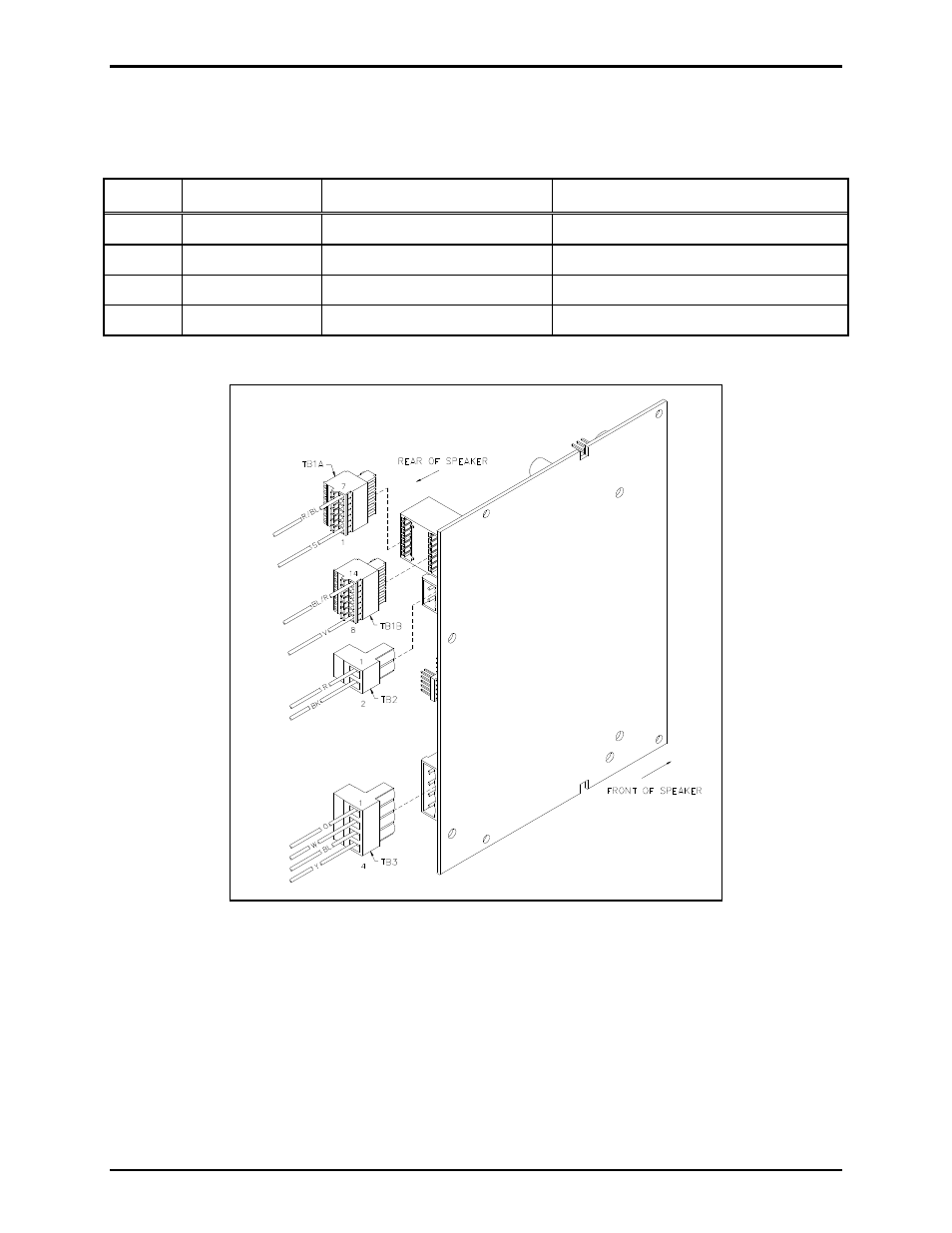
TB3 Wiring Connector
The numbering orientation is shown in Figure 8.
Table 7. TB3 Wiring Description
Pin No. Pin Name
Connection
Function
1
S
PEAKER
O
UT
+
Internal Speaker
Class D audio speaker audio
2
S
PEAKER
O
UT
−
Internal Speaker
Class D audio speaker audio
3
R
ELAY
O
UT
NO
TB101-10
Normally open relay connection
4
R
ELAY
O
UT
C
OM
TB101-9
Common relay connection
Figure 8. TB1 (A & B), TB2, and TB3 Connector Orientation Diagram
Closing the Addressable Amplified Speaker
When wire terminations have been completed, reconnect the dual 7-point connectors (TB1A and TB1B),
the 2-point connector (TB2), and 4-point connector (TB3) to the PCBA. Route the wires through the
nylon tie. Refer to Figure 8 for connector orientation and location. Re-twist the nylon tie to secure the
wires. Refer to Figure 5 for wire routing. Assemble the speaker sections and tighten the front panel
screws to 16 to 20 in-lbs. of torque.