Block diagram – GAI-Tronics 723-901 SmartSeries Remote Subset Amplifier User Manual
Page 5
Pub. 42004-326C
Model 723-901 SmartSeries
®
Remote Subset Amplifier
Page 5 of 13
f:\standard ioms - current release\42004 instr. manuals\42004-326c.doc
03/12
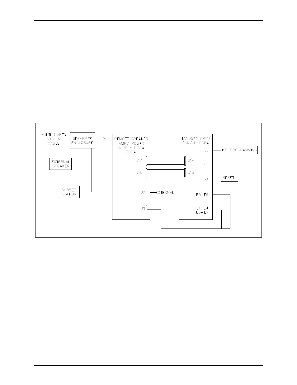
Block Diagram
The P1 connector on the back of the Remote Speaker Amp/Power Supply PCBA plugs into a socket in an
enclosure connected to the system cable, accessing the Page/Party
®
lines and ac power. The Remote
Speaker Amp/Power Supply PCBA contains the low voltage power supplies and the speaker amplifier
circuitry.
Connector J1A and J1B on the Remote Speaker Amp/Power Supply connects regulated +5 V dc, +/−15 V
dc, and V
RLY
voltages along with control, monitoring, and line signals to the J1A and J1B on the Handset
Amp/FSK/
P PCBA. Connector J2 of the Remote Speaker Amp/Power Supply PCBA connects to
optional external devices.
The Handset Amp/FSK/
P PCBA has connections to the handset and the hookswitch via spade terminal
connectors E1 to E7, and it connects via J3 on the Remote Speaker Amp/Power Supply PCBA.
Figure 3. Remote Subset Amplifier Block Diagram