Annex – Flowserve TRV5-40 User Manual
Page 24
4
Node ID
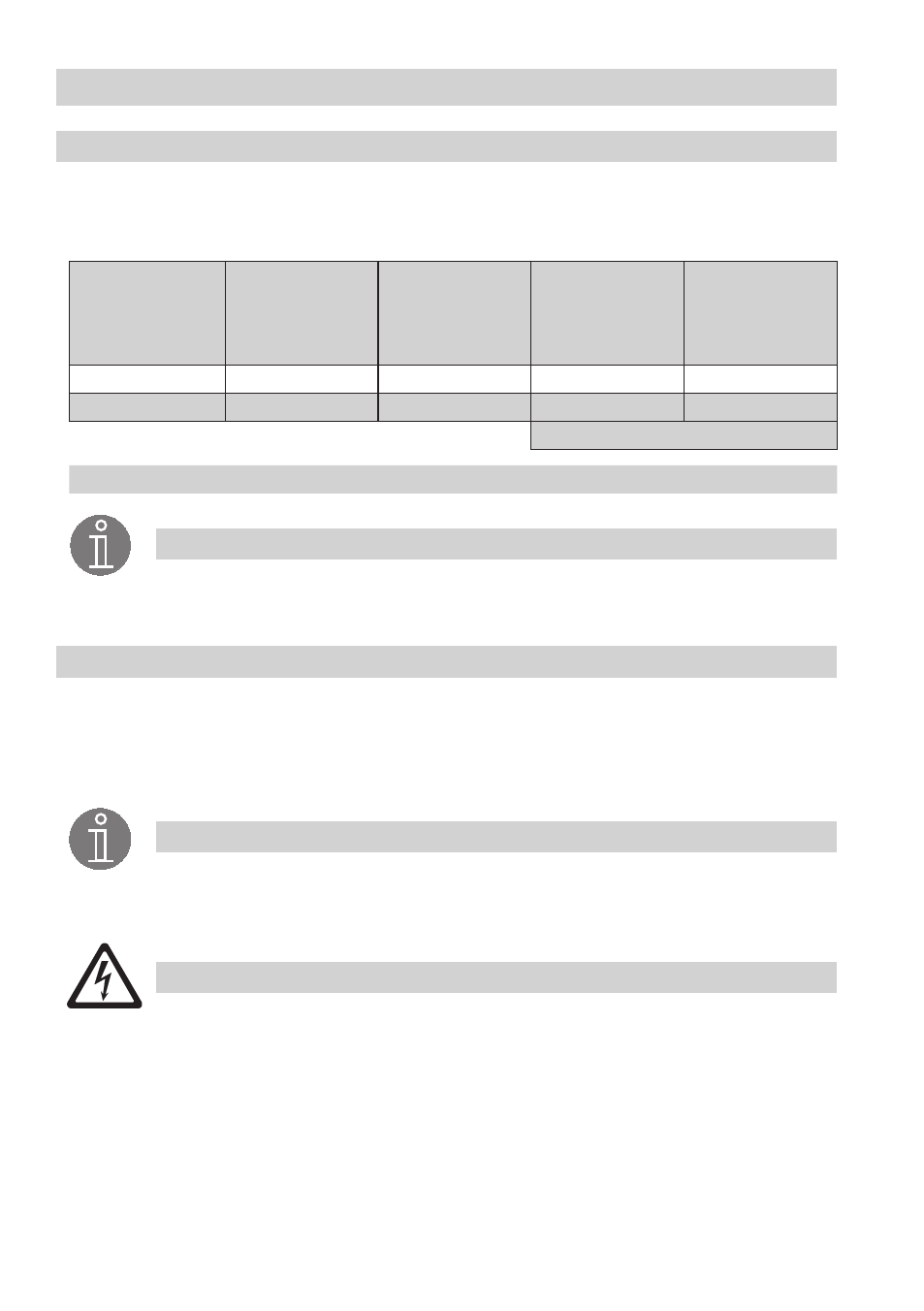
Should it be necessary to establish other node IDs please take the interdependence of the equipment
into consideration and assign the node ID for the individual group components according to the following
table:
Control unit
NRS 1-40.1
Sensor 1
e. g.
level electrode
NRG 1x-40
as first device
Sensor 2
e. g.
level electrode
NRG 1x-40
as second device
Sensor 3
e. g.
level electrode
NRG 1x-41.1
Sensor 4
e. g.
temperature
transmitter
TRV 5-40
X
X + 1
X + 2
X + 3
X + 4
1
2
3*
4
5
Factory setting
Reserved area
Annex
– continued –
Note
The node ID
3* for the second level electrode NRG x-40 must be set in situ because
the default factory setting is .
Changing node ID for safety part
When the housing is open:
Use a thin blade screwdriver to set switches S to S7 of the code switch
F Fig. 3 in accordance with
table “Node ID”.
Enter the adjusted node ID on the name plate.
Note
The two node IDs for the two actual value outputs (part for temperature monitoring and
control) are linked with the node ID of the safety part and cannot be adjusted. For more
information see the installation manual of the control unit TRS 5-40.
Attention
Do not use a node ID for more than one item of equipment in the CAN bus system.
The node ID 0 is not permissible.