Commissioning – Flowserve TRV5-40 User Manual
Page 15
5
Commissioning
– continued –
Examples of configuration settings
Example
The following items of equipment are connected to the control unit NRS -40.:
Level electrodes NRG x-40 for low water level LW and
Level electrode NRG x-4. for high water level HW and
Temperature transmitter TRV 5-40 for MAX temperature
As only in the temperature transmitter TRV 5-40 the limiter number can be adjusted, the control unit
NRS -40. has to be configured as follows:
Limiter
B
B
B3
B4
Function
Water level LW 1
Water level LW 2
High water HW
Temperature MAX
Set the temperature transmitter TRV 5-40 as limiter 4.
Example
The following items of equipment are connected to the control unit NRS -40.:
Level electrodes NRG x-40 for water level LW and and
Temperature transmitter TRV 5-40 for MAX temperature
Limiter
B
B
B3
B4
Function
Water level LW 1
Water level LW 2
Temperature MAX
Set the temperature transmitter TRV 5-40 as limiter 3.
Changing system configuration
– continued –
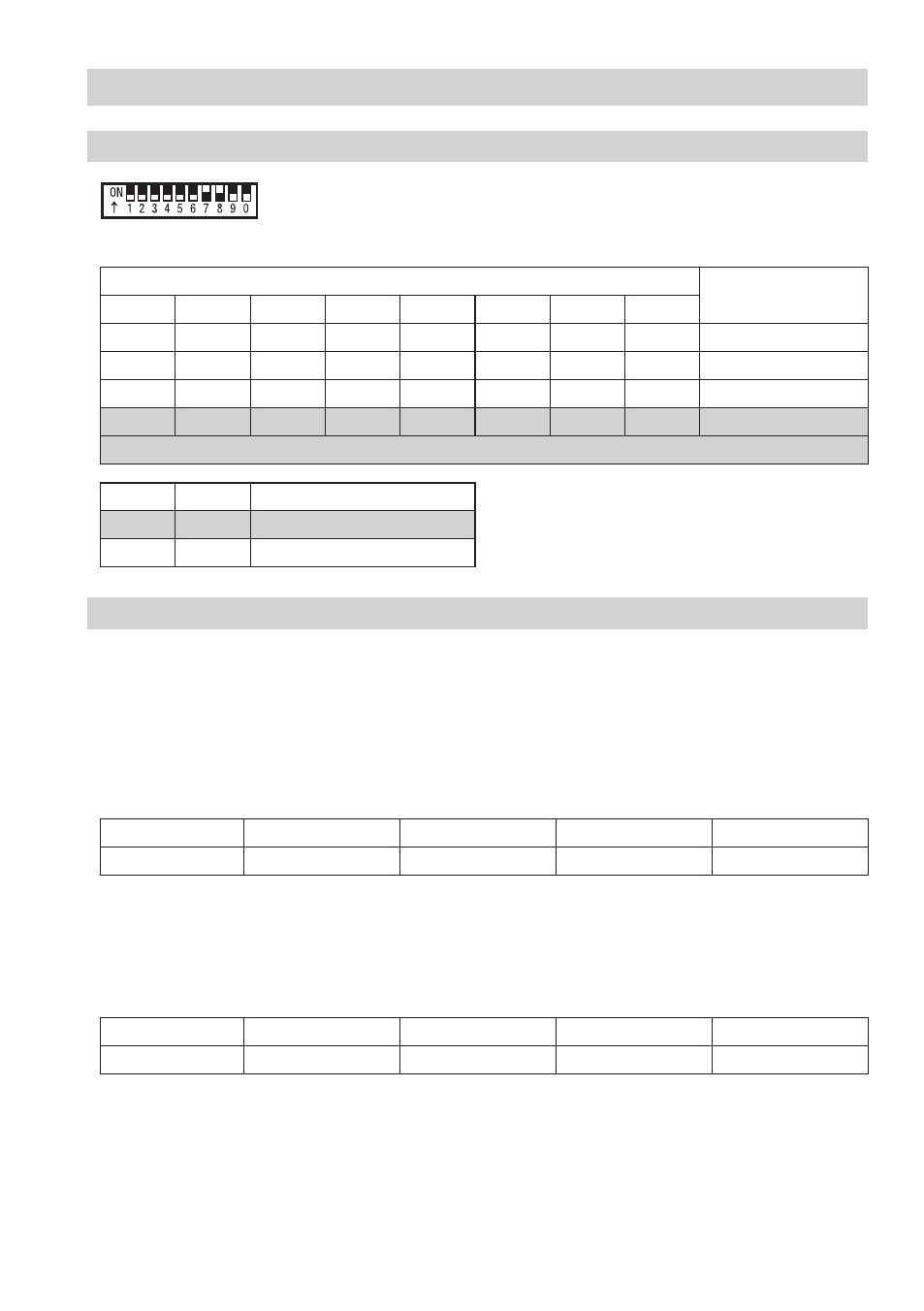
G
Toggle switch white
Code switch
G
Limiter
Number
S
S
S3
S4
S5
S6
S7
S8
ON
ON
OFF
OFF
OFF
OFF
OFF
OFF
OFF
OFF
ON
ON
OFF
OFF
OFF
OFF
OFF
OFF
OFF
OFF
ON
ON
OFF
OFF
3
OFF
OFF
OFF
OFF
OFF
OFF
ON
ON
4
Factory setting
S9
S0
Communication with control unit
OFF
OFF
NRS -40.
ON
ON
NRS -40.