Start, operation and test, Fig. 6 – Flowserve TRV5-40 User Manual
Page 17
7
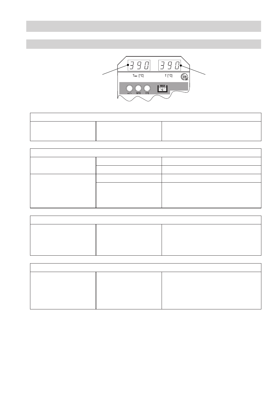
Start
Apply supply voltage.
All segments and decimal
points of the displays
T
MAX
and T are flashing.
The LED displays are being tested.
Operation
Actual value T (°C) below limit
value T
MAX
(°C)
Display T
MAX
Indication of the adjusted limit
Display T
Indication of the actual value
Actual value T (°C) above limit
value T
MAX
(°C)
Display T
MAX
Indication of the adjusted limit
Display T
Indication of the actual value and triggering of
an alarm.
Control unit NRS -40. / NRS -40. opens the
output contacts after the time delay has elapsed.
Test
The pushbutton for the TRV
5-40 on the
control unit NRS
1-40.1 / NRS 1-40.2 must be
pressed and held down until
the test is finished.
Display T
An increase in temperature is simulated and
the indicated actual value rises steadily. When
the adjusted limit value is exceeded, the control
unit NRS -40. / NRS -40. opens the output
contacts after the time delay has elapsed.
Indication of an error code
When an error occurs
Display T
Display switches between indication of error
code (E xx) and actual value T. The control unit
NRS -40. / NRS 40. opens instantaneously
the output contacts and the output of terminal
7,8 is energised/de-energised in a time-
controlled manner.
Start, Operation and Test
TRV 5-40
Fig. 6
Indication of
limit value
Indication of
actual value / error code