8 basic operation, 9 hart, 10 position definition – Flowserve 420 IOM User Manual
Page 4: 11 command input and final command, Asic, Peration, Hart, Osition, Efinition, Ommand
User Instructions - Logix® 420 Series Digital Positioners FCD LGENIM0106-06 12/13
flowserve.com
4
form of cover plates, especially where side-mounted
positioners are fitted. If these plates are removed for
inspection, service or repair special attention is required.
After completing work the cover plates must be refitted.
Logix 420 positioner repair is limited to the replacement of
sub-assemblies and circuit boards with FLOWSERVE-
manufactured replacements as outlined in this manual.
DANGER: Substitution of with non-factory positioner
components may impair intrinsic safety.
CAUTION:
Before
products
are
returned
to
FLOWSERVE for repair or service, FLOWSERVE must be
provided with a certificate which confirms that the product
has been decontaminated and is clean. FLOWSERVE will
not accept deliveries if a certificate has not been provided (a
form can be obtained from FLOWSERVE).
Apart from the operating instructions and the obligatory
accident prevention directives valid in the country of use, all
recognized regulations for safety and good engineering
practices must be followed.
PRINCIPLES OF OPERATION
1.8 Basic Operation
The Logix 420 digital positioner is a two-wire 4-20 mA input
digital valve positioner which uses the HART protocol to
allow two-way remote communications. The positioner is
completely powered by the 4-20 mA input signal. Start-up
current must be at least 3.8 mA. The positioner is
configurable through the local user interface, hand-held or
DTM. The Logix 420 positioner can control single-acting
pneumatic actuators with linear or rotary mountings.
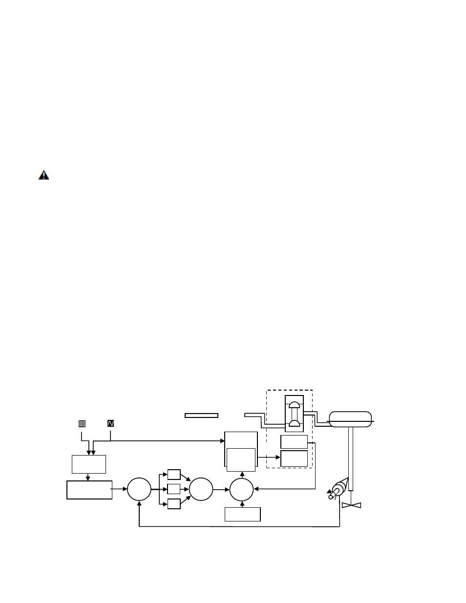
The Logix 420 digital positioner is an electronic and
pneumatic closed-loop feedback instrument. Figure 1 shows
a schematic of a Logix 420 positioner installed on a single-
acting linear actuator for air-to-open action.
1.9 HART
The Logix 420 receives power from the two-wire, 4-20 mA
input signal. However, since this positioner utilizes HART
communications, two sources can be used for the command
signal: Analog and Digital. In Analog source, the 4-20 mA
signal is used for the command source. In Digital source, the
level of the input 4-20 mA signal is ignored (used only for
power) and a digital signal, sent via the HART
communication protocol, is used as the command source.
The command source can be accessed with ValveSight
software, the HART 375 communicator, or other host
software. See section 11 HART COMMUNICATION
1.10 Position Definition
Whether in Analog or Digital Source, The position at 0% is
always defined as the valve in a closed position and 100% is
always defined as the valve in an open position. In Analog
Source, the 4-20 mA signal is converted to a position (in
percent). During loop calibration, the signals corresponding
to 0% and 100% are defined.
1.11 Command Input and Final Command
The Command Input signal (in percent) passes through a
characterization/limits modifier block. This function is done in
software, which allows for in-the-field customer adjustment.
The characterization block can apply no adjustment (Linear),
one
of
several
pre-defined
characterization
curve
Figure 1: Principles of Operation of Logix 420
Piezo
Valve
Hall
Sensor
Air Supply
Poppet
Valve
Single Acting
Pilot Relay
Piezo
Voltage
Piezo Kill
Circuit
Inner
Loop
Spool
Control
Position
Feedback
Control
Valve
Actuator
Final
Command
Command
Input
Signal
Characterization,
Soft Limits,
Tight Shutoff
Digital
Command
Input
Analog
Command
Input
(4-20 mA)
Output
Percentage
+
+
+
Σ
P
I
D
Σ
+
_
Inner-Loop
Output
+
_
Σ
Inner-Loop
Offset