6 tubing, 1 determine air action, 2 connect supply port – Flowserve 420 IOM User Manual
Page 11: 3 vented design, 4 purging, Tubing, Etermine, Ction, Onnect, Upply
User Instructions - Logix® 420 Series Digital Positioners FCD LGENIM0106-06 12/13
flowserve.com
11
6
TUBING
After mounting has been completed, tube the positioner to
the actuator using the appropriate compression fitting
connectors. For best performance, use 10 mm (3/8 inch)
tubing for 645 square cm (100 square inch) actuators or
larger.
6.1 Determine Air Action
The port labeled “Out” delivers air when an air supply is
present and the relay is energized. This port should be tubed
to the pneumatic side of the actuator (the side that would
result in the air compressing the actuator spring). When
tubed this way, the spring is designed to return the valve to
the fail safe state should supply air or power to the unit fail.
If air from the output should open the valve, set the Air Action
configuration switch on the positioner to Air-to-Open,
otherwise set it to Air-to-Close.
The Air-to-Open and Air-to-Close selection is determined by
the actuator assembly, not the software.
6.2 Connect Supply Port
The positioner ports are threaded with 1/4 NPTF. The direct
mount output is 1/16 NPTF.
In order to maintain the recommended air quality, a
coalescing filter should always be installed in the supply gas
line. An air filter is highly recommended for all applications
where dirty air is a possibility. The positioner passage ways
are equipped with small filters, which remove medium and
coarse size dirt from the pressurized air. If necessary, they
are easily accessible for cleaning.
In applications where the supply pressure is higher than the
maximum actuator pressure rating a supply regulator is
required to lower the pressure t
o the actuator’s maximum
rating.
6.3 Vented Design
A standard Logix 420 positioner is vented directly to the
atmosphere. When supply air is substituted with sweet
natural gas, piping must be used to route the exhausted
natural gas to a safe environment.
The exhaust port is located on the bottom of the positioner.
The port is tapped with either ¼ NPTF threads and covered
with a protective cap. To control vented gas, remove the cap
and connect the necessary tubing/piping to this port.
This piping system may cause some positioner back
pressure.
The maximum allowable back pressure from the exhaust port
is 0.14 barg (2.0 PSIG). For output flow rates, see section 2.4
Pneumatic Output.
CAUTION: The back pressure in the main housing must
never rise above 0.14 barg (2.0 PSIG). This could cause the
positioner
to
become
unresponsive
under
some
circumstances.
6.4 Purging
Purging is intended to supply the non-pressurized side of a
single acting actuator with instrument air. This helps prevent
air from the environment (which may be salty, dirty or humid)
from corroding the springs and other actuator components.
Purging uses exhaust air from the positioner to flush the
spring side of the actuator.
Tubing Configuration -
Tube the Exhaust port with a “T”
where one line goes to the non-pressurized side of the
positioner and the second line goes to the atmosphere.
Install an exhaust plug on the second line to prevent debris
from entering the tubing.
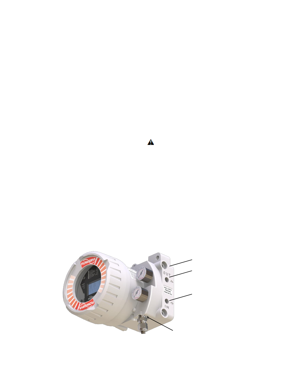
Exhaust (Piezo and
Actuator)
(0.14 barg (2 psi) Max)
Figure 5: Pneumatic Ports
Out
(Direct
Mount
Control)
Out
(Control)
In
(Supply)