2 scrolling status messages, 3 current alarm status, 4 status icons – Flowserve 420 IOM User Manual
Page 20: 5 adjusting the display contrast
User Instructions - Logix® 420 Series Digital Positioners FCD LGENIM0106-06 12/13
flowserve.com
20
10.1.2 Scrolling Status Messages
The Scrolling Status Message provides the following
information as applicable:
Ambient Temperature
– This is the temperature inside the
positioner.
DIP Switch Override
– This indicates that the Configuration
(DIP) Switches do not reflect the actual configuration of the
positioner. This can happen if a Configuration Switch is
changed after a Quick-Cal, or if the configuration is was
changed from the DTM. Performing a Quick-Cal will reset
the configuration to what the Configuration Switches show,
which may not be desirable. Ensure the Configuration
Switches are set properly before performing a Quick-Cal.
10.1.3 Current Alarm Status
The Current Alarm Status area shows the highest priority
alarm, warning, alert or status indication. This matches the
code indicated by the flashing LEDs.
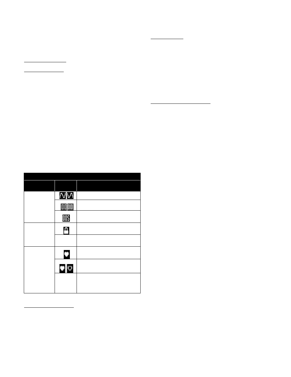
10.1.4 Status Icons
Status icons continuously show the state of the features and
modes.
Table 12: Status Icons
Icon Location
Icon
Icon Meaning
Command
Source
Analog command mode
Digital command mode
Out of service
Pressure
Control
Pressure control locked
(blank)
Pressure control not locked
HART
Communicatio
ns
HART communication currently in
progress
Burst mode in progress
(blank)
No HART communication currently
in progress
Command Source Icons
– The positioner is in Analog
Command mode if it is using the 4-20 mA signal to control
the location of the valve. In Digital Command mode, the
positioner ignores the 4-20 command and responds to the
position command given through HART. In Out Of Service
mode, the positioner is performing a calibration, signature,
partial stroke test or is in a factory reset state.
Pressure Control
– When the position of the valve gets very
close to the commanded position, the positioning algorithm
will change to pressure control. This means the pressures
will be held constant (locked), improving the stability of the
valve position. The point at which the pressure control is
locked depends on the Valve Stability switch on the
positioner. When the switch is set to “Lo Friction”, the locking
point is self-adjusting to optimize accuracy. When the switch
is set to “Hi Friction” and the deviation is smaller than +/-
1.0%, the
pressure “locks”. This value can be adjusted using
the Display Menu or DTM. See section 10.3.7 Configuration
(Pressure Control
HART Communications Icons
– When the positioner is
sending or receiving data via the HART communication
protocol, the icon will be displayed. During burst mode, a
pulsating heart icon will be displayed.
10.1.5 Adjusting the Display Contrast
To adjust the display contrast, hold the
◄ Back button for 3
seconds. Use the
▲Up and ▼ Down buttons to adjust the
contrast. Use the
►ACCEPT/QUICK-CAL to accept the
settings.