13 maintenance and repair, 1 scheduled maintainance, 2 required tools and equipment – Flowserve 420 IOM User Manual
Page 30: 3 replacing a main board, Maintenance and repair, Cheduled, Aintainance, Equired, Ools and, Quipment
User Instructions - Logix® 420 Series Digital Positioners FCD LGENIM0106-06 12/13
flowserve.com
30
13
MAINTENANCE AND REPAIR
The kits listed in section 16.2 Spare
replaced by a technician trained in positioner function and
handling of static sensitive devices.
CAUTION: Depressurize the positioner before
servicing.
CAUTION: Use eye protection.
CAUTION: When touching the circuit boards, observe
precautions for handling electrostatically sensitive devices.
13.1 Scheduled Maintainance
The supply gas filter(s) should be scheduled for regular
maintenance as required to maintain supply gas quality. If
contamination is found in the filter, the inside of the
positioner should be visually inspected for contamination.
If contamination is found in the positioner, the positioner
should be replaced.
13.2 Required Tools and Equipment
The Logix 420 digital positioner has modular components
that can be replaced using these tools:
Figure 15: Tools for Positioner Maintenance
13.3 Replacing a Main Board
Removal
1
Make sure the valve is bypassed or in a safe
condition.
2
Remove the outer cover.
3
Disconnect the power to the positioner.
4
Remove the inner cover by removing the 3 retaining
screws.
5
Gently lift the main board rotating the bottom up while
keeping the top in place.
6
Disconnect the hall sensor cable, the piezo cable and
the feedback cable. Use a small flat screwdriver to
press in the locking features and carefully separate
the connector from the main board. Be careful not to
pull the cable, as this may cause damage to the
cable.
Installation
1
Place the main board on the positioner base with the
4-20 mA input on the same side as the electronic
access ports.
2
Lift the main board rotating the bottom (configuration
switches) upwards while keeping the top in place.
3
Connect the pressure sensor board cable, the hall
sensor cable, and the feedback cable. Ensure the
connector’s locking features engage.
4
Place the main board on the positioner base, ensuring
the cables are clear of the feedback gears.
5
Replace the inner cover by inserting the 6 retaining
screws.
6
Calibrate.
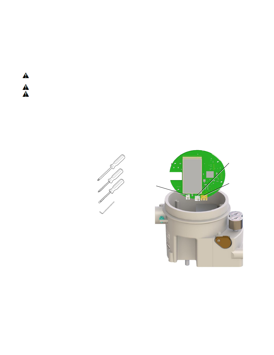
Figure 16: Main Board Connectors
Feedback
Pot
Connector
Piezo
Connector
Hall
Sensor
Connector
Philips Screwdriver #2 _______
Philips Screwdriver #1 _______
Flat Screwdriver _______
2.5 mm Hex Driver _______