11 hart communication, 1 valvesight dtm, 2 hart 475 handheld communicator – Flowserve 420 IOM User Manual
Page 27: 3 burst mode, 4 changing hart versions, Hart communication, Alve, Ight, Hart, Andheld
User Instructions - Logix® 420 Series Digital Positioners FCD LGENIM0106-06 12/13
flowserve.com
27
11
HART COMMUNICATION
The Logix 420 series positioners use the HART
communication
protocol
specified
by
the
HART
Communication Foundation.
11.1 ValveSight DTM
Flowserve Corporation has produced a custom Device
Type Manager (DTM) for the Logix 420 digital positioner to
support the ValveSight diagnostics platform.
The DTM contains a high level “Dashboard” view of the
system health and status information. It also contains
comprehensive user-friendly interfaces for control and
reporting of alarms, of-line and on-line diagnostic tests,
calibrations and system configurations.
The ValveSight DTM is available from a Flowserve
representative or from www.valvesight.com.
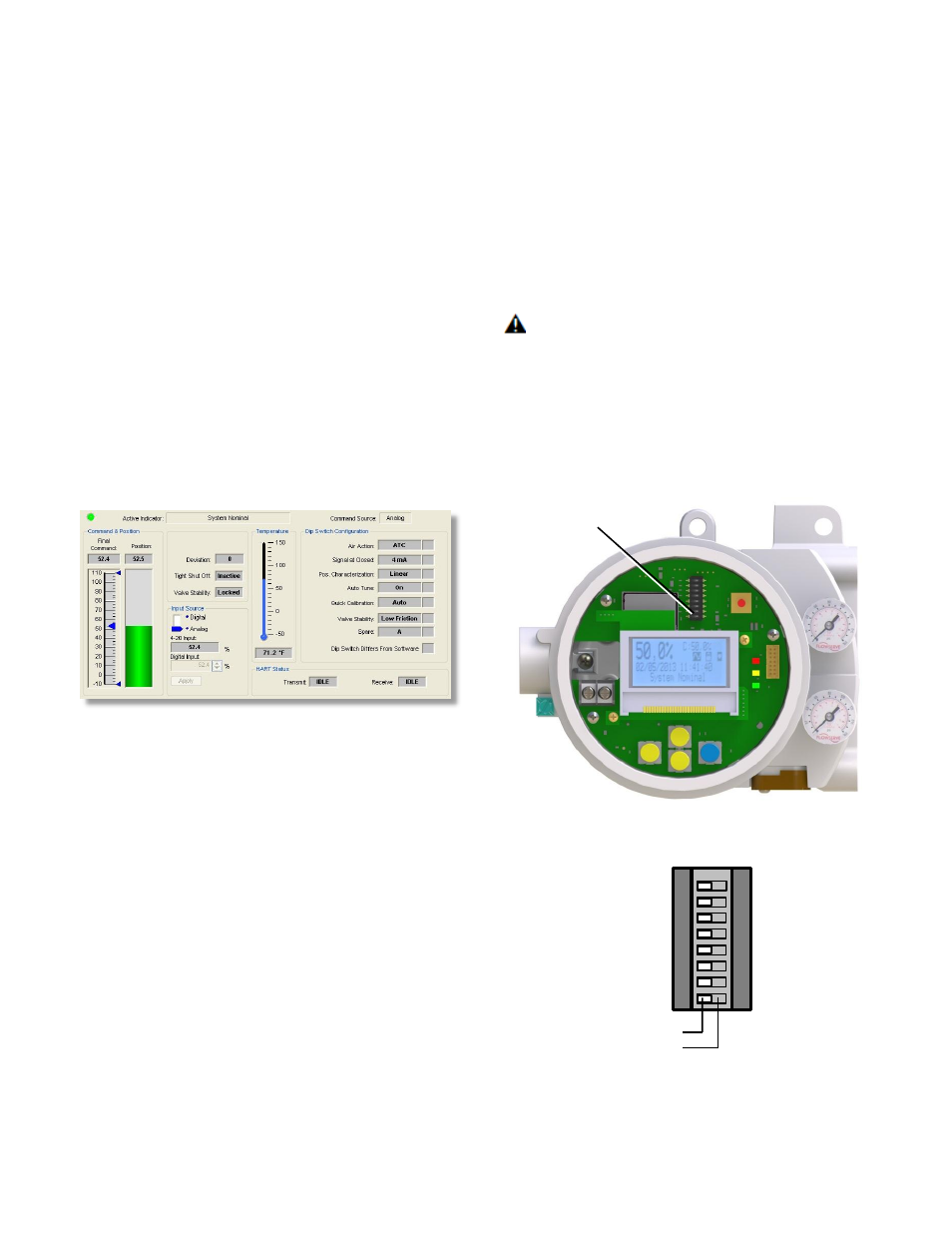
Figure 13: ValveSight DTM Dashboard
11.2 HART 475 Handheld Communicator
The Logix 420 digital positioner supports and is supported
by the HART 475 Handheld Communicator. The Device
Description (DD) files can be obtained from the HART
Communication Foundation or from your Flowserve
representative.
11.3 Burst Mode
Burst Mode is available with a handheld device. In the
menu of the handheld, select the Burst Mode feature under
the Configuration Menu.
NOTE: The DTM will not function while the positioner is in
Burst Mode.
11.4 Changing HART Versions
The Logix 420 positioner comes standard with the HART 6
communication protocol. Follow this procedure to change
to HART 7.
1
Remove the outer cover.
2
Remove the inner cover by removing the 3 inner
cover retaining screws.
CAUTION: Observe precautions for handling
electrostatically sensitive devices.
3
With a clean, non-conductive instrument, change the
position of DIP switch according to Figure 14: HART
DIP Switch. After changing the DIP switch, the
positioner will immediately recognize the new HART
communication protocol.
4
Replace the covers.
Figure 14: HART DIP Switch
HART DIP
Switch
HART 6
HART 7
1
2
3
4
5
6
7
8