14 troubleshooting, 1 troubleshooting guide, Troubleshooting – Flowserve 420 IOM User Manual
Page 31: Roubleshooting, Uide
User Instructions - Logix® 420 Series Digital Positioners FCD LGENIM0106-06 12/13
flowserve.com
31
14
TROUBLESHOOTING
14.1 Troubleshooting Guide
Table 15: Troubleshooting Guide
Failure
Probable Cause
Corrective action
No LED is blinking.
1. Current source too low.
2. Voltage of current source is too low.
3. Incorrect wiring polarity.
1. Verify current source supplies at least 3,8 mA.
2. Verify voltage source supplies at least 10VDC.
3. Check wiring for correct polarity.
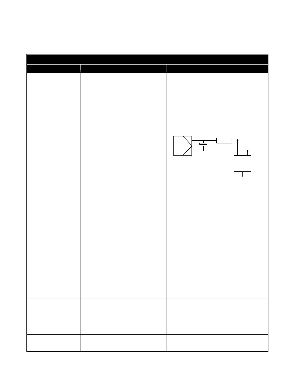
Erratic communications.
1. Current source bandwidth not
limited to 25Hz.
2. Maximum cable length or cable
impedance exceeded.
3. HART modem connected to PC RS-232
port not receiving enough power
4. Interference with I.S. barrier.
5. Current source stripping (filtering)
HART signal.
1. Maximum allowable current source rate of
change is 924 mA per second.
2. Check cable size, length and capacitance. See
Section 7 ELECTRICAL CONNECTIONS.
3. Verify laptop battery is not low.
4. Must use HART compatible I.S. barrier.
5. Use a
250Ω resistor and a 22 µF capacitor to
create a HART filter according to the following
schematic.
Unit does not respond
to analog commands.
1. The positioner is in digital
command mode.
2. An error occurred during
calibration.
1. Switch to analog command mode using
the procedure outlined in Section 9.3
Command Source Reset, use the
ValveSight DTM, or use a handheld
communicator.
2. Check Status Codes. Correct calibration
error. Recalibrate.
Valve position reading
is not what is
expected.
1. Stem position sensor mounting is
off 180 degrees.
2. Stroke not calibrated
3. Tight shutoff (MPC-Minimum
position cutoff) is active.
4. Custom characterization or soft
stops are active.
1. Reposition the sensor.
2. Perform a Stroke calibration (Quick-Cal).
3. Verify Tight Shutoff settings.
4. Verify custom characterization or soft-stop limits.
Position is driven fully
open or closed and will
not respond to
command.
1. Stroke is not calibrated.
2. Inner-loop hall sensor is not connected.
3. Wrong air action was entered in
software.
4. Actuator tubing is backward.
5. Electro-pneumatic converter
is malfunctioning.
6. Control parameter inner-loop offset
is too high/low.
1. Perform stroke calibration (Quick-Cal)
2. Verify hardware connections.
3. Check ATO (Air-to-open) and ATC (Air-to-
Close) settings. Recalibrate using Quick-Cal to
apply settings.
4. Verify ATO/ATC actuator tubing.
5. Replace electro-pneumatic converter.
6. Adjust inner-loop and see if proper control
resumes.
Sticking or hunting
operation of the positioner
1. Contamination of the electro-pneumatic
converter.
2. Control tuning parameters not correct.
3. Packing friction is high.
1. Check air supply for proper filtering and meeting
ISA specifications ISA-7.0.01.
2. Lower proportional gain settings.
3. Enable the stability DIP switch on the local
interface and recalibrate. If problem persists,
adjust pressure control window with handheld
communicator or ValveSight and recalibrate.
LCD backlight flickering or
dim.
1. The backlight uses any residual power
not used by other functions of the
circuitry.
1. Fluctuations in the LCD backlight are normal.
No action required.
22 µF 250Ω
Control
System
HART
Comm
Device
→
To Logix