Flowserve Chemstar standard User Manual
Page 32
CHEMSTAR USER INSTRUCTIONS ENGLISH 71569185 02-10
Page 32 of 44
flowserve.com
c) Lightly lubricate repeller cover gasket [4610.5]
with non abrasive hand soap and install it in the
dedicated groove. If repeller pump model is
Group C size C100x65M-315A, C125x80M-400
or C150x125M-400, refer to the close-up views of
the cover gasket joint in section 8.3 or 8.4.
Assemble the metallic ring spacer [3126] so that
the side without writing is placed in contact with
the repeller cover gasket [4610.5]. Inspect the
gasket ring spacer [4610.7] for any damage or
defects; replace it with a new one if there are any
doubts. Carefully slide the gasket ring spacer
over the repeller cover [1220.4] and hand push it
until it touches the metallic ring spacer in a
complete circle.
d) Install the rear cover [1220.1] by sliding it over
the repeller cover. Install the mounting ring (see
section 6.5) and fasten it with nuts as shown in
the following pictures.
Tighten all the nuts on the mounting
ring so that the repeller cover gasket [4610.5] is
compressed evenly otherwise the nominal
impeller clearances may not be achieved.
Note that a mounting ring is not needed
for the Group C sizes 400 repeller pumps
e) The impeller and impeller clearance can now be
set following the instructions in section 6.7.3.
6.11 Sealing arrangements
6.11.1 Sealing arrangement assembly
Contact your nearest Flowserve sales office or
service centre if you require further information or are
unsure of the specific seal arrangement supplied.
Refer also to section 4.6.5, Auxiliary piping.
6.11.2 Single seal in TE (FMI) rear cover
This section shows details of the basic seal
arrangement with the Seal Sentry TE (FMI) rear
cover. To assemble the arrangement:
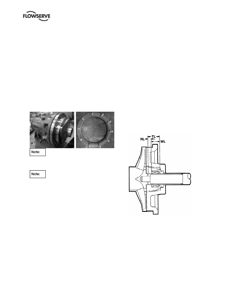
a) Refer to the TE (FMI) rear cover drawing below.
b) Having checked the impeller clearance is correct,
install mechanical seal stationary seat into the
rear cover counterbore.
c) Measure the distance TL from the seal face on
the stationary seat to the end of the hook sleeve,
or equivalent position on a solid shaft (if fitted).
d) The seal working length, WL, is determined from
the seal drawing provided by the seal
manufacturer. Subtract the seal working length
WL from TL.
e) The distance remaining, RL, is the distance from
the end of the hook sleeve or solid shaft (if fitted)
to the rotating unit. Install the rotating unit of the
component seal at this location.
f) If a hooked sleeve is fitted, the rotating unit
should be set in position on this. Install the hook
sleeve assembly onto the shaft.
g) Reinstall the impeller onto the shaft, locking the
hook sleeve into position.