Flowserve Chemstar standard User Manual
Page 30
CHEMSTAR USER INSTRUCTIONS ENGLISH 71569185 02-10
Page 30 of 44
flowserve.com
6.10.5 Assembly of bearing housing into casing
a) Fit a new gasket [4590.1] on rear cover as shown
above.
b) Install the bearing housing assembly into the
pump casing. Coat the screws with anti-galling
compound and tighten into casing.
c) Check impeller clearance against original setting,
or process requirement and adjust as necessary.
(See section 6.7, Setting impeller clearance.)
d) Ensure that all other items have been re-attached
and all fasteners tightened, then follow the
instructions in section 4, Installation and section 5,
Commissioning.
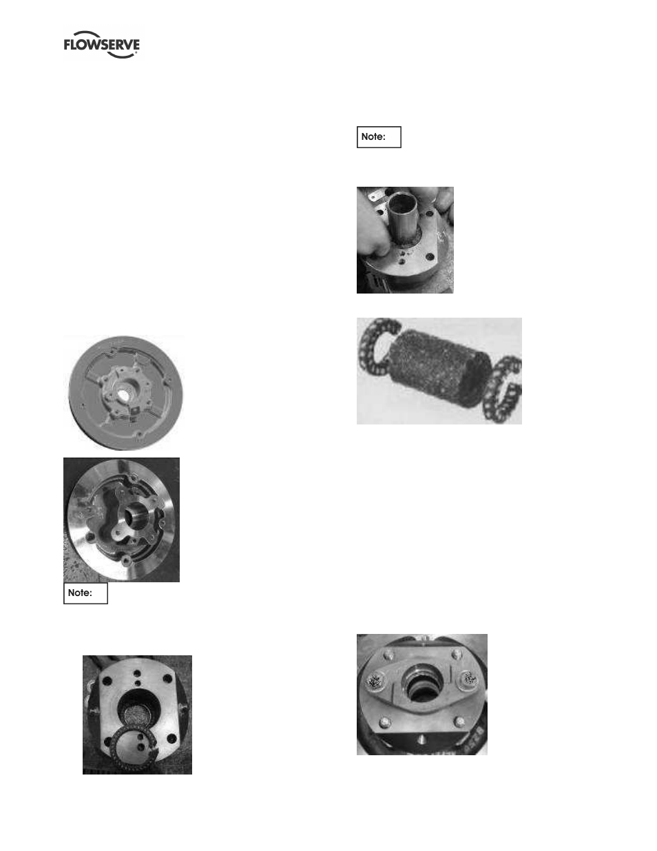
6.10.6 Repeller pump: installation of gland
packing
The stuffing box bore in which the gland packing is
installed is either a separate stuffing box [1220.3]
bolted into the large bore repeller cover or the stuffing
box of the small bore repeller cover (1220.4). Both
the options have identical stuffing box dimensions.
Use disposable plastic gloves for the
following actions:
a) Clean the stuffing box bore. Insert one packing
ring [4130.1] and push it against the bottom of
the stuffing box cavity.
b) Place a 43 or 53 mm diameter smooth bar or
pipe (depending if Group B or C pump) at the
centre of the bore and insert the injectable
packing compound [4130.2] into the stuffing box.
85 g of injectable packing is required to
fill the stuffing box chamber. Flowserve provides
the exact amount of injectable packing required
when it is ordered as a spare part.
c) Insert another packing ring into the stuffing box on
top of the injectable packing
d) Assemble the two studs [6572.2] in the stuffing
box of the repeller cover [1220.4] or in a separate
stuffing box [1220.3] depending on the
configuration.
e) Assemble the gland follower halves [4120.2], slide
assembly into the stuffing box engaging the studs
[6572.2] in holes. Tighten the nuts[6580.3]
loosely. Using a thickness feeler gage blade in
between the gland and stuffing box face, tighten
the nuts alternately until 3 mm (
⅛
in.) residual
clearance is reached.
f) For repeller pumps with large bore repeller cover
[1220.2], install the stuffing box assembly into the
repeller cover.
g) For repeller pumps with small bore repeller cover
mount the repeller cover assembly onto the
bearing housing [3200].
Large bore repeller cover
assembled with separate
bolt-on stuffing box
Small bore repeller cover
with built in stuffing box