Flowserve Chemstar standard User Manual
Page 26
CHEMSTAR USER INSTRUCTIONS ENGLISH 71569185 02-10
Page 26 of 44
flowserve.com
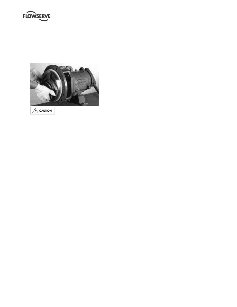
c) Give the impeller a quick turn counter-clockwise
to strike the wrench handle against the
workbench surface or a hard surface on the left-
hand side. Several sharp raps in this way will free
the impeller from the shaft so it may be
unscrewed.
d) The impeller has an O-ring that should be
discarded. Use a new O-ring for assembly.
Do not attempt to remove or place
the impeller on the shaft by hitting the impeller
with a hammer or using a poorly fitting pry bar
between the impeller vanes. Serious damage to
the impeller may result from such actions.
6.8.3 Rear cover and seal
The seal manufacturer's instructions should be
followed for dismantling and assembly, but the
following guidance should assist with most seal types:
a) Remove internal shaft guard or seal guard (if fitted).
b) Remove the seal follower nuts [6572.2], if a
separate seal follower [4131] is fitted, and slide
the follower away.
c) Remove the rear cover retaining screws [1220].
d) Loosen the grub screws (used in most
mechanical seals) on some seal rotaries.
e) Carefully pull off the rear cover and mechanical
seal rotating element(s) if not furnished with a
hook type sleeve.
f) Remove the seal follower [4131]/complete
cartridge seal (if fitted).
g) Remove shaft hooked sleeve (if fitted) together
with seal rotary. Be certain to measure and
record the position of the seal rotary unit on the
sleeve. A replacement seal rotary of the same
type may then be relocated at the same position
on the same or a new hook type sleeve.
h) On non-cartridge seals the stationary seat
remains in the seal follower/cover with its sealing
member. Remove only if damaged or worn out.
i)
On pumps fitted with gland packing, the packing
[4130] and lantern ring [4134] should be removed
only if the packing is to be replaced.
6.8.4 Bearing housing
a) Pull off the pump half of the coupling (if not
previously removed) and remove the coupling
key [6700].
b) Remove support foot (if necessary).
c) Loosen the three set screws [6570.3] in the
bearing carrier [3240].
d) Remove bearing carrier and shaft assembly from
the bearing housing [6700] by using a spanner
wrench to engage the slots on the bearing carrier.
Rotate this counter-clockwise a number of turns
until the carrier outer threads disengage the
bearing housing.
e) Because the O-ring [4610.3] may cause slight
resistance to removing the bearing carrier
assembly from the bearing housing [3200], hold
the bearing carrier flange firmly and with slight
rotation and pull it to the rear.
f) Remove the pump side deflector [2540] or labyrinth
seal rotary half [4330.1], depending on option fitted.
g) The carrier assembly with shaft and bearings
should come out towards the coupling end.
h) Remove bearing snap ring [2530] or clamp ring
[3240.1].
i)
Remove drive side liquid flinger or labyrinth seal
rotary half [4330.2] if fitted.
j)
Remove the bearing carrier from the bearing [3013].
k) When pressing bearings off the shaft, use even
pressure force on the inner race only. An arbor
or hydraulic press may be used to remove the
bearings.
l)
Now remove pump side bearing [3011].
m) The bearing locknut [3712] and lockwasher
[6541] may now be removed from the shaft.
n) Remove drive side bearing [3013].
6.8.5 Repeller pump
a) Remove the casing [1100]. With Group C pumps
remove the ring spacer [3126] and ring spacer
gasket [4610.7], if used. Except for C400 pump
sizes, the impeller [2200] cannot rotate freely as
the repeller cover gasket [4610.5] is pressing the
rear cover [1220.1] onto the impeller which
closes in the impeller clearance. For C400 sizes
proceed directly to c) below.
b) Install the mounting ring as described in section
6.10.9. The impeller will then rotate freely.
c) Remove the impeller as shown in section 6.8.2. For
safety reasons, screw a nose cone into the shaft
end to temporarily lock the repeller on the shaft.
d) If pump is C400 size, remove the mounting ring
or the hold down screws [6570.5] and slide the
rear cover [1220.1] away from the repeller cover
[1220.2]. To help removal use a levering action
by wedging a pry-bar into the groove formed at
the outer rims of the assembled covers.