Flowserve Chemstar standard User Manual
Page 31
CHEMSTAR USER INSTRUCTIONS ENGLISH 71569185 02-10
Page 31 of 44
flowserve.com
6.10.7 Repeller pump - installation of repeller
cover
See sectional drawing in section 8.3.
a) Install the packing as described in section 6.10.6.
b) For pumps supplied with a large bore repeller
cover, place the flat gasket [4590.2] on the
bottom of the cover bore and slide the stuffing
box unit assembly into the bore and fasten it with
screws [6570.6].
c) Lubricate the shaft and cone with a film of
silicone. Screw the shaft guide or nose cone on
the shaft end threads. Install the repeller cover
[1220.2] over the shaft and push it all the way
back until it contacts the flange face of the
bearing housing and becomes piloted by the
counterbore. Hold the repeller cover using two
capscrews [6570.7].
For Group B315 pumps there are two
special capscrews [6570.9].
For Group C400 pumps, install the repeller cover
[1220.2] to the bearing housing [3200] flange
using capscrews [6570.5].
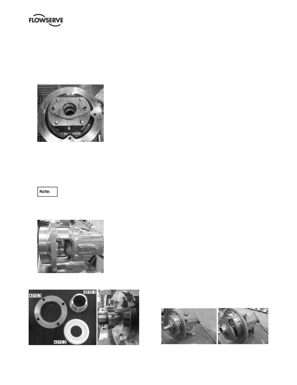
6.10.8 Reassembly - repeller pump with FXP seal
(secondary sealing)
See sectional drawing in section 8.6.
a) Remove any sharpness of edge at wet end of
shaft with #400 emery cloth.
b) Clean all exposed surfaces of the wet end of the
shaft.
c) Install a shaft guide (or nose cone) tool from the
Flowserve tool kit. (See section 6.5.)
d) Insert the O-rings into the grooves on the inside
diameter of the seal rotor.
e) Lubricate the O-rings and shaft with non-abrasive
liquid hand soap and slide the drive collar
[4310.1] onto the shaft until it contacts the
bearing housing.
f) Place repeller cover face down on workbench
and set the Teflon disk [4310.2] against the gland
surface (ie end of stuffing box). Attach gland
[4310.3] to repeller cover and screw on gland
nuts finger-tight.
g) Reinstall the repeller cover, repeller, rear cover,
and impeller as described in section 6.7.3 and
6.10.9.
h) Tighten gland nuts fully. Slide the drive collar
forward until it contacts the Teflon disk.
i)
To preload the seal, push the drive collar against
the Teflon disk by applying even pressure. The
drive collar should be pushed into the Teflon disk
approximately 3mm (
⅛
in.). Tighten the drive
collar setscrews while maintaining pressure on
the drive collar.
j)
Once the pump is flooded, check the seal to ensure
it is not leaking. If the seal leaks, repeat step i)
above, applying only enough pressure to the drive
collar to stop the leak. Do not over tighten the seal.
6.10.9 Repeller pump - assembly of repeller, rear
cover and impeller
See sectional drawing in section 8.3.
a) Install a repeller O-ring [4610.6] into the groove in
the central hollow in the repeller hub. Lubricate
the O-ring with liquid soap or a grease compatible
with the material of the O-ring.
b) Carefully slide the slip-on repeller [2200.1] onto
the shaft, taking care not to damage the repeller
O-ring with the shaft end edges. (Remove the
nose cone before assembling the repeller.)
Follow instructions in section 6.10.4 to screw in
the impeller [2200] and strongly clinch the
repeller onto the shaft. Set the repeller clearance
as explained in section 6.7.3. Remove the
impeller.