4 recommended spares, 5 tools required – Flowserve Chemstar standard User Manual
Page 23
CHEMSTAR USER INSTRUCTIONS ENGLISH 71569185 02-10
Page 23 of 44
flowserve.com
6.4 Recommended spares
For two years operation (as per VDMA 24296)
Number of pumps
(including stand-by)
Part no. Designation
2
3
4
5
6/7
8/9
10(+)
2200
Impeller
1
2
3
30%
2100
Shaft
1
2
3
30%
6541
Lockwasher
1
2
3
4
50%
2400
Shaft sleeve, if fitted
2
3
4
50%
3011
Bearing - inboard
1
2
3
4
50%
3013
Bearing - outboard
1
2
3
4
50%
4590.1 Gasket - cover
4
6
8
9
12
150%
4590.4
Gasket seal
follower, if fitted
4
6
8
9
10
100%
4610.1 O-ring - impeller
4
6
8
9
12
150%
4610.3 O-ring - carrier
4
6
8
9
10
100%
4310.1 Oil seal - inboard
4
6
8
9
10
100%
4310.2 Oil seal - outboard
4
6
8
9
10
100%
4130
Gland packing ring
- set
2
3
4
40%
4120
Gland halves
1
2
3
30%
2540
Deflector
1
2
3
30%
-
Mechanical seals
1
2
3
30%
-
Power end
-
-
-
-
-
1
2
4130.2 Injectable packing
2
3
4
40%
4610.1 O-ring - repeller
4
6
8
9
12
150%
4610.5 Gasket - repeller
cover
4
6
8
9
10
100%
6.5 Tools required
A typical range of tools that will be required to
maintain these pumps is listed below.
Readily available in standard tool kits, and dependent
on pump size:
•
Open ended spanners (wrenches) to suit up to
M 48 screws/nuts
•
Socket spanners (wrenches), up to M 48 screws
•
Allen keys, up to 10 mm (A/F)
•
Range of screwdrivers
•
Soft mallet
•
Thickness feeler gages
More specialized equipment:
•
Bearing pullers
•
Bearing induction heater
•
Dial test indicator
•
C-spanner (wrench) - for removing shaft nut.
(If difficulties in sourcing are encountered, consult
Flowserve.)
•
Coupling grip/shaft spanner
•
Nose cone for shaft impeller side
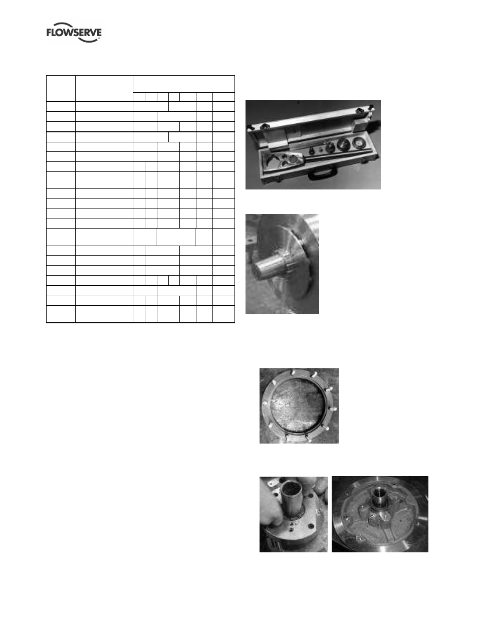
To simplify maintenance, it is recommended that the
Flowserve Chemstar tool kit (shown below) be used.
[Flowserve Part # MISCRK00068AA]. This tool kit can
be ordered from your local Flowserve sales engineer or
from a Flowserve distributor or representative.
The tool kit contains “nose cones” (shown below) which
protect shaft threads and O-rings during maintenance.
The following tools are required for disassembly and
assembly of repeller pumps.
•
Mounting ring (see below). Rings are available
for sizes B250, B315 and C250/315 pumps.
(Size C400 does not require a mounting ring.)
•
Bar diameter 43 and 53 mm. To facilitate setting
injectable packing in stuffing box of repeller
covers. (Refer to section 6.10.6.)