Flowserve Chemstar standard User Manual
Page 12
CHEMSTAR USER INSTRUCTIONS ENGLISH 71569185 02-10
Page 12 of 44
flowserve.com
Although the pump will have been aligned at the factory
it is most likely that this alignment will have been
disturbed during transportation or handling. If
necessary, align the motor to the pump, not the pump to
the motor.
Alignment is achieved by adding or removing shims
under the motor feet and also moving the motor
horizontally as required. In some cases where the
alignment cannot be achieved it will be necessary to
move the pump before recommencing the above
procedure.
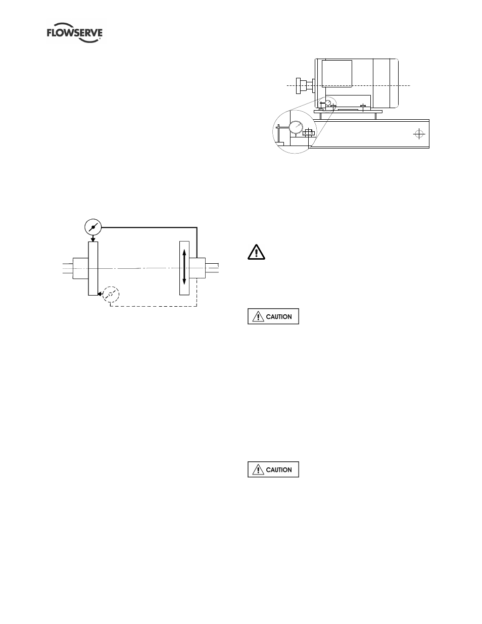
For couplings with narrow flanges use a dial indicator as
shown. Rotate both shafts together so that the dial
indicator probe keeps the same contact point onto the
flange during 360 degree rotation. The alignment
values are maximums for continuous service.
Parallel
Angular
Permissible misalignment limits at working
temperature:
•
Parallel alignment
- 0.25 mm (0.010 in.) TIR maximum
•
Angular alignment
- 0.3 mm (0.012 in.) TIR maximum for couplings
not exceeding 100 mm (4 in.) flange diameter
- 0.5 mm (0.020 in.) TIR maximum for couplings
over 100 mm (4 in.) diameter
When checking parallel alignment, the total indicator
read-out (TIR) shown is twice the value of the actual
shaft displacement.
Align in the vertical plane first, then horizontally by
moving motor. Maximum pump reliability is obtained by
near perfect alignment of 0.05 - 0.075 mm (0.002 -
0.003 in.) parallel and 0.05 mm (0.002 in.) per 100 mm
(4 in.) of coupling flange diameter as angular
misalignment.
4.5.3 Check for soft foot
This is a check to ensure that there is no undue
stress on the driver holding down bolts; due to non-
level baseplate or twisting. To check, remove all
shims and clean surfaces and tighten down driver to
the baseplate.
Set a dial indicator as shown in sketch and loosen off
the holding down bolt while noting any deflection
reading on the dial test Indicator - a maximum of
0.05 mm (0.002 in.) is considered acceptable but any
more will have to be corrected by adding shims. For
example, if the dial test indicator shows the foot lifting
0.15 mm (0.006 in.) then this is the thickness of shim
to be placed under that foot. Tighten down and
repeat the same procedure on all other feet until all
are within tolerance
Complete piping as below and see section 4.7,
Final shaft alignment check up to and including section
5, Commissioning, startup, operation and shutdown,
before connecting driver and checking actual rotation.
4.6 Piping
Protective covers are fitted to the pipe
connections to prevent foreign bodies entering during
transportation and installation. Ensure that these
covers are removed from the pump before connecting
any pipes.
4.6.1 Suction and discharge pipework
In order to minimize friction losses and hydraulic
noise in the pipework it is good practice to choose
pipework that is one or two sizes larger than the
pump suction and discharge. Typically main
pipework velocities should not exceed 2 m/s (6 ft/sec)
suction and 3 m/s (9 ft/sec) on the discharge.
Take into account the available NPSH which must be
higher than the required NPSH of the pump.
Never use pump as a support for
piping.
Maximum forces and moments allowed on the pump
flanges vary with the pump size and type. To minimize
these forces and moments that may, if excessive, cause
misalignment, hot bearings, worn couplings, vibration
and the possible failure of the pump casing, the
following points should be strictly followed: