6 fastener torques, 7 setting impeller clearance – Flowserve Chemstar standard User Manual
Page 24
CHEMSTAR USER INSTRUCTIONS ENGLISH 71569185 02-10
Page 24 of 44
flowserve.com
6.6 Fastener torques
Fastener position
Fastener
size
Torque
Nm (lbf ft)
Casing, rear cover,
repeller cover and
bearing housing foot
M8
M10
M12
M16
M20
16 (12)
25 (18)
35 (26)
80 (59)
130 (96)
Mechanical seal follower
(gasket type seal only).
(Others as rear cover)
M10
M12
13 (10)
34 (25)
Bearing carrier
M10
M12
15 (11)
35 (26)
Bearing retainer lock
ring capscrews
3/16
5/16
3 (2)
8 (6)
Non-metalic gaskets incur creep
relaxation - before commissioning the pump check
and retighten fasteners to tightening torques stated.
6.7 Setting impeller clearance
This procedure may be required after the pump has
been dismantled or a different clearance is required.
Before carrying out this procedure ensure that the
mechanical seal(s) fitted can tolerate a change in
their axial setting, otherwise it will be necessary to
dismantle the unit and reset the seal axial position
after adjusting the impeller clearance.
a) Disconnect the coupling if it has limited axial
flexibility.
b) The impeller adjustment on the Chemstar is
easily made externally by loosening the set
screws [6570.3] and rotating the bearing carrier
[3240] to obtain the proper clearance.
6.7.1 Setting reverse vane impeller rear clearance
Impeller clearance setting
Temperature
All impeller diameters
50 ºC (120 ºF)
100 ºC (210 ºF)
150 ºC (300 ºF)
200 ºC (390 ºF)
260 ºC (500 ºF)
0.45 mm (0.018 in.)
0.55 mm (0.022 in.)
0.65 mm (0.026 in.)
0.75 mm (0.030 in.)
0.85 mm (0.033 in.)
a) Turn the bearing carrier counter-clockwise until
the impeller comes into light contact with the rear
cover. Rotating the shaft at the same time will
accurately determine when a detectable rub is
obtained. This is the zero clearance setting.
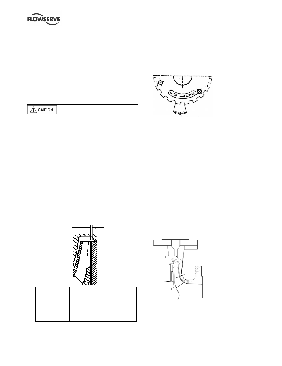
b) Rotating the bearing carrier the width of one notch
on the bearing carrier, as shown below, moves
the impeller axially by 0.05 mm (0.002 in.).
Rotation equivalent to 0.1 mm
(0.004 in.) axial movement
Example: for an impeller setting of 0.45 mm
(0.018 in.) simply move the carrier clockwise nine
notches for the required clearance.
c) Use the notch closest the parting line on the top
centre of the bearing housing as the reference
point to begin adjustment.
d) After obtaining the proper clearance, listed in the
table above, tighten the set-screws evenly to lock
the impeller and shaft assembly. Because of the
slight draw as the carrier/housing threads lock it
may be necessary to allow for this change. If
possible, check results with a feeler gauge.
e) If a cartridge seal is fitted it should be reset at this
point.
f) Check that the shaft can turn freely without
binding.
g) Ensure the coupling distance between shaft ends
(DBSE) is correct. Reset/re-align if necessary.
6.7.2 Setting high chrome iron front open
impeller clearance
a) Turn the bearing carrier clockwise until the impeller
comes into light contact with the front profile on the
casing. Rotating the shaft at the same time will
accurately determine when a detectable rub is
obtained. This is the zero clearance setting.
Reverse vane
impeller rear
clearance