0 auxiliaries, 1 seal and seal systems – Flowserve WUC Worthington User Manual
Page 43
WUC USER INSTRUCTIONS ENGLISH - 07/14
Page 43 of 52
6.9.5 Assembly of the thrust bearing
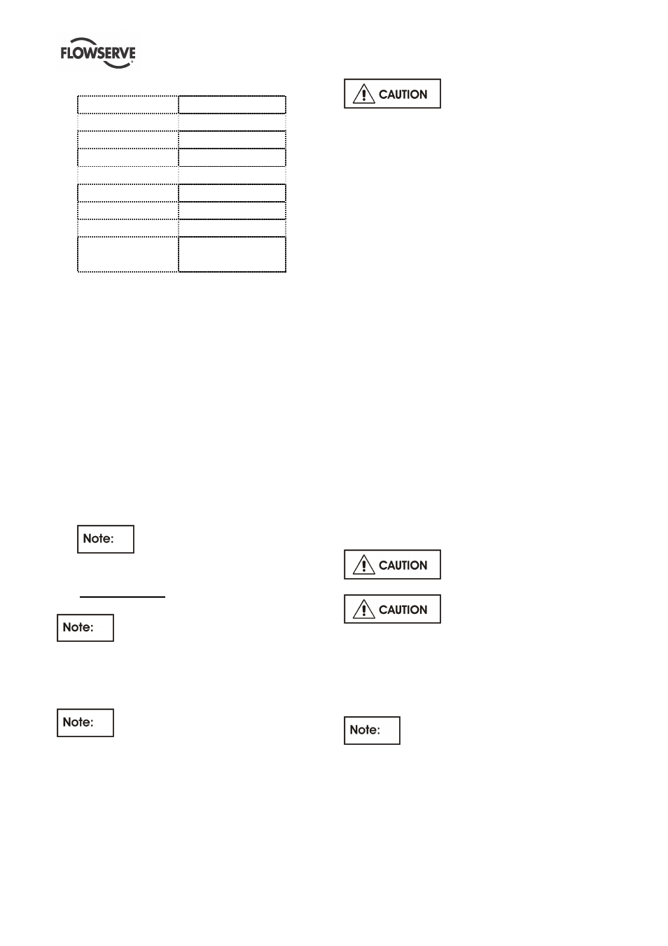
Thrust bearing No.
Bearing size
0 N
7210 BECBJ (M)
1 N
7313 BECBJ (M)
3 N
7315 BECBJ (M)
4 N
7317 BECBJ (M)
5 N
7318 BECBJ (M)
6 N
7322 BECBM
7 N
7326 BCBM
8 N
7232 BCBM
7330 BCBM
6.9.5.1 Bearing housing 3N – 8N
1) Heat up the first angular contact bearing, and put
it on the bearing adaptor sleeve [2471] as shown
in the section drawing.
2) Install the spacer ring [2510]. Warm up the other
two bearings and install it according to the
section drawing. Put on the lockwasher [6541] for
bearing nut and the bearing lock nut [3712]. After
tightening secure the bearing lock nut [3712] with
the lockwasher [6541] for bearing nut.
6.9.5.2 Bearing housing 0N – 1N
1) Heat up the two bearings and install it according
to the section drawing.
2) Put on the lockwasher [6541] for bearing nut and
the bearing lock nut [3712]. After tightening
secure the bearing lock nut [3712] with the
lockwasher [6541] for bearing nut.
For the hydrodynamic thrust bearing
assembly refer to bearing manufacturer´s IOM.
7.0 AUXILIARIES
For additional accessories refer to
separate Instrumentation manuals.
7.1 Seal and seal systems
7.1.1 Single Mechanical Seal with API–Plan 23+61
Refer to mechanical seal drawing and
auxiliary piping drawing.
The pump is equipped with a single mechanical seal.
The cartridge design allows to change the
mechanical seal without taking it apart.
Actions before first start up:
The pump will be delivered with correct vertical
adjustment of the rotor.
Try to turn the rotor by hand.If
the rotor cannot be turned readjust it following
procedure in section 5.3.1 Adjusting of the rotor.
The mechanical seal requires no adjustment
anymore. Check if the mounting plates are
alreadyswung out.
Actions after start up:
Check all connections to the seal gland and the
mechanical seal itself against leakage. It is usual that
at the seal faces a small leakage occurs after start
up, which decreases with the time of operation and
should stop after the seal is run in. Check the
temperature of the seal gland. I slight increase of
temperature may be observed during the run in
period. The mechanical seal is flushed by an API
Plan 23 and the temperature at the seal gland should
be below the pumped liquid temperature (refer to
mechanical seal drawing for temperature limit).
Plan 23 is the plan of choice for all hot water
services, and it is also disirable in many hydrocarbon
and chemical services where it is necessary to cool
the fluid establish the required margin between fluid
vapor pressure (at the seal chamber temperature)
and seal chamber pressure. In a Plan 23, the cooler
only removes seal face-generated heat plus heat
soak from the process. The seal chamber is isolated
by a pump throat bushing with a bypass to suction.
API Plan 61 has tapped and plugged connections for
the purchaser´s use. Typically this plan is used when
the purchaser is to provide fluid (such as steam, gas, or
water) to an external sealing device.
Refer to the GA - drawing for the
required quench medium, pressure and flow.
Disassembly of the seal cartridge
is only allowed by authorized personal. Contact
Flowserve for any service of the mechanical seal. We
recommend to have a spare cartridge seal on stock
for easy replacement.
7.1.2 Dual Mechanical Seal unpressurized with
API–Plan 13+52+61
Refer to mechanical seal drawing and
auxiliary piping drawing.
The pump is equipped with a dual mechanical seal.
The cartridge design allows to change the
mechanical seal without taking it apart.
Actions before first start up:
The pump will be delivered with correct vertical
adjustment of the rotor.