9 assembly – Flowserve WUC Worthington User Manual
Page 41
WUC USER INSTRUCTIONS ENGLISH - 07/14
Page 41 of 52
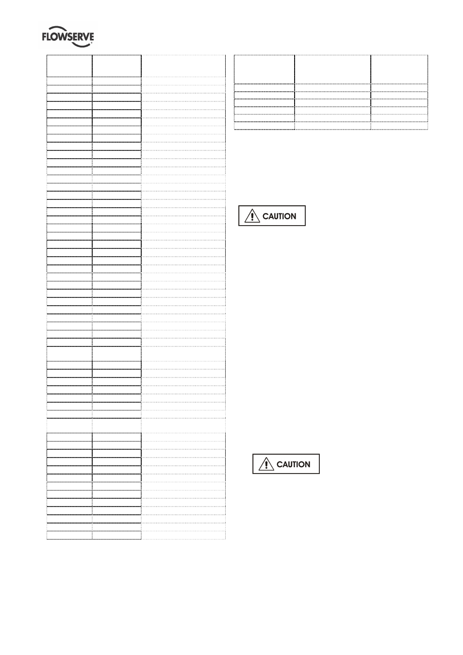
Pump size
Wear ring
diameter mm
(in)
Radial clearances
mm (in)
10 WU-2H
64 (2.5)
0.3 - 0.5 (0.012-0.020)
20 WU-2L
64 (2.5)
0.3 - 0.5 (0.012-0.020)
20 WU-2R
112 (4.4)
0.4 - 0.6 (0.016-0.024)
25 WU-2R
115 (4.5)
0.4 - 0.6 (0.016-0.024)
30 WU-2R
112 (4.4)
0.4 - 0.6 (0.016-0.024)
35 WU-2R
112 (4.4)
0.4 - 0.6 (0.016-0.024)
40 WU-2H
95 (3.7)
0.4 - 0.6 (0.016-0.024)
45 WU-2L
87 (3.4)
0.3 - 0.5 (0.012-0.020)
45 WU-2R
112 (4.4)
0.4 - 0.6 (0.016-0.024)
50 WU-2R
112 (4.4)
0.4 - 0.6 (0.016-0.024)
50 WU-2M
85 (3.3)
0.4 - 0.6 (0.016-0.024)
50 WU-2H
140 (5.5)
0.5 - 0.7 (0.020-0.028)
60 WU-2M
85( 3.3)
0.4 - 0.6 (0.016-0.024)
60 WU-2R
112 (4.4)
0.4 - 0.6 (0.016-0.024)
65 WU-2R
148 (5.8)
0.5 - 0.7 (0.020-0.028)
80 WU-2L
103 (4.1)
0.4 - 0.6 (0.016-0.024)
80 WU-2H
148 (5.8)
0.5 - 0.7 (0.020-0.028)
90 WU-2R
148 (5.8)
0.5 - 0.7 (0.020-0.028)
100 WU-2R
148 (5.8)
0.5 - 0.7 (0.020-0.028)
100 WU-2M
120 (4.7)
0.5 - 0.7 (0.020-0.028)
125 WU-2L
120 (4.7)
0.5 - 0.7 (0.020-0.028)
150 WU-2R
169 (6.7)
0.5 - 0.7 (0.020-0.028)
150 WU-2M
125 (4.9)
0,5 - 0.7 (0.020-0.028)
180 WU-2L
135/171(5.3/6.7) 0.5 - 0.7 (0.020-0.028)
200 WU-2M
160 (6.3)
0.5 - 0.7 (0.020-0.028)
200 WU-2L
160 (6.3)
0.5 - 0.7 (0.020-0.028)
200 WU-2R
169 (6.7)
0.5 - 0.7 (0.020-0.028)
200 WU-2H
140/165(5.5/6.5) 0.5 - 0.7 (0.020-0.028)
200 WU-4M
180 (7.1)
0.5 - 0.7 (0.020-0.028)
250 WU-4H
200 (7.9)
0.6 - 0.8 (0.024-0.032)
275 WU-2M
160 (6.3)
0.5 - 0.7 (0.020-0.028)
300 WU-2R
183 (7.2)
0.5 - 0.7 (0.020-0.028)
300 WU-4H
230(9.1)
0.6 - 0.8 (0.024-0.032)
300 WU-4M
190/230(7.5/9.1)
0.5 - 0.7 / 0.6 - 0.8 (0.020-
0.028 / 0.024-0.032)
300 WU-2L
160/190(6.3/7.5) 0.5 - 0.7 (0.020-0.028)
400 WU-4R
236 (9.3)
0.6 - 0.8 (0.024-0.032)
400 WU-4M
240 (9.5)
0.6 - 0.8 (0.024-0.032)
400 WU-4H
240 (9.5)
0.6 - 0.8 (0.024-0.032)
450 WU-2R
183 (7.2)
0.5 - 0.7 (0.020-0.028)
500 WU-2L
191 (7.5)
0.5 - 0.7 (0.020-0.028)
600 WU-4M
265 (10.4)
0.6 - 0.8 (0.024-0.032)
650 WU-2L
190/230(7.5/9.1)
0.5 - 0.7 / 0.6 - 0.8 (0.020-
0.028 / 0.024-0.032)
700 WU-4H
265 (10.4)
0.6 - 0.8 (0.024-0.032)
800 WU-4M
300 (11.8)
0.6 - 0.8 (0.024-0.032)
900 WU-4M
265 (10.4)
0.6 - 0.8 (0.024-0.032)
900 WU-4H
300 (11.8)
0.6 - 0,8 (0.024-0.032)
1000 WU-4H
300 (11.8)
0.6 - 0,8 (0.024-0.032)
1200 WU-4H
330 (13.0)
0.7 - 0.9 (0.028-0.035)
1200 WU-4L
330 (13.0)
0.7 - 0.9 (0.028-0.035)
1400 WU-4M
354 (13.9)
1 - 1.2 (0.039-0.047)
1500 WU-4L
339 (13.4)
0.7 - 0.9 (0.028-0.035)
1600 WU-4M
339 (13.4)
0.7 - 0.9 (0.028-0.035)
2000 WU-4L
360 (14.2)
1 - 1.2 (0.039-0.047)
2000 WU-4M
360 (14.2)
1 - 1.2 (0.039-0.047)
2250 WU-4L
388 (15.3)
1 - 1.2 (0.039-0.047)
6.9 Assembly
To assemble the pump consult the sectional
drawings.
Ensure threads, gasket and O-ring mating faces are
clean. Apply thread sealant to non-face sealing pipe
thread fittings.
After complete assembly with
headstock and bearing housing the rotor must be
lifted!, see section 5 .3 Impeller clearance
6.9.1 Assembly of radial flow impeller pump types
Assembly is done preferably in vertical position.
1) Put the last stage diffuser [1410.2] into the
discharge casing [1140]. Insert the O-ring
[4610.5]. Repeat this with all the stage casings
[1160], diffusers [1410.1] and O-rings [4610.5].
2) Put the discharge casing [1140] over the pump
shaft [2110].
3) Put in the key [6700.3] in the keyway and slip on
the interstage sleeve [2410.2], the last stage
impeller [2200.1] and the interstage sleeve
[2410.1] to the shaft.
4) Put on the next stage casing assembly. Put the
key [6700.3] in the keyway and slip on the
impeller [2200.1] and the interstage sleeve
[2410.1] to the shaft.
5) Repeat step 4 until you reach the first stage. After
slipping on the first stage impeller [2200.2] and
the interstage sleeve [2410.2] you can put on the
suction casing [1130].
6) Fix the hydraulic assembly by tightening the tie
bolts [6571].
This must be done croswise
with required torques.(refer to section 6,
Maintenance)
7) Put on the distance sleeve [2460], or inducer
[2215] and secure the assembly by tightening the
impeller nut [2912] just by hand.
8) Loose the impeller nut [2912] to the next location
for securing it with a grub screw [6814.2].
9) For further pump assembly follow reverse
disassembly procedure.
Bearing Sleeve
Outside Diameter
[mm]
Pipe Bearing Housing
Bushing Inner
Diameter
[mm]
Radial
clearance
[mm]
Ø31,9
Ø32
0,10÷0,12
Ø51,9
Ø52
0,10÷0,12
Ø59,9
Ø60
0,11÷0,13
Ø71,9
Ø72
0,11÷0,13
Ø109,9
Ø110
0,12÷0,15
Ø119,9
Ø120
0,12÷0,15