5 piping – Flowserve WUC Worthington User Manual
Page 19
WUC USER INSTRUCTIONS ENGLISH - 07/14
Page 19 of 52
4.5 Piping
4.5.1 General
Protective covers are fitted to the pipe connections to
prevent foreign particles entering during
transportation and installation. Ensure that these
covers are removed from the pump before
connecting any pipes.
Maximum forces and moments allowed on the pump
flanges vary with the pump size and type. To
minimize these forces and moments which may
cause misalignment, hot bearings, worn couplings,
vibration and a possible failure of the pump, the
following points shall be strictly followed:
a) Prevent excessive external pipe load.
b) Do not connect piping by applying external force
(use of wrenches, crane,...). Piping shall be
aligned without residual stress.
c) Do not mount expansion joints so that their force,
due to internal pressure, acts on the pump
flange.
Fitting an isolator and non-return valve can allow
easier maintenance. Never throttle pump on suction
side and never place a valve directly on the pump
inlet nozzle.
A non-return valve shall be located in the discharge
pipework to protect the pump from excessive
backpressure and hence reverse rotation when the
unit is stopped.
Piping and fittings shall be flushed before use. To
avoid damages of the pump install a strainer of 40
meshes.
Piping for corrosive liquids shall be arranged to allow
pump flushing before removal of a unit.
4.5.2 Vent
The extent of venting requirements depends on the
application and installation requirements.The
following instructions may be used as a guide insofar
as they apply to the pump as delivered. For type,
position and dimensions of the vent connections
please see GA drawing.
Do not mix up connections. After
laying the pipes (and also after repairs), check the
pipe runs.
4.5.2.1 General recommendation
Vent valves are generally installed at one or more
high points of the pump casing waterways. They are
used to facilitate priming of the pump and to prevent
trapping of air or vapor in the casing during operation.
Pumps handling flammable, toxic, or corrosive fluids
require vent piping connected in such a way that the
safety of operating personnel and the installation is
ensured (i.e. to the suction tank). The suction vents
of pumps taking liquids from a closed vessel under
vacuum must be piped to the gas phase of the
suction tank.
Venting lines shall continuously rise up in order to
avoid air/gas entrapment.
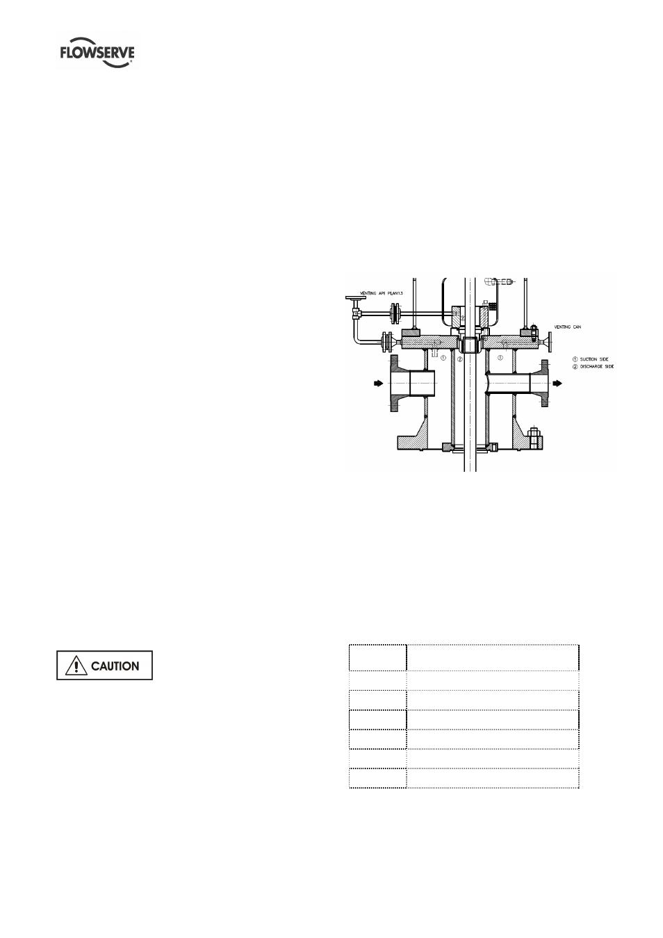
A vent connection for the suction can and a vent
connection for API Plan 13 are Flowserve standard
supply in order to allow venting of both, the suction
and discharge areas of the pump. For pumps
supplied with gas coffer dam only the suction CAN
will be fitted with a vent connection.
The vent piping is not within Flowserve scope of
supply.
Fig.1 Venting of the suction and discharge areas of the pump
4.5.2.2 Standard design
Prior to start-up the pump must be vented through
connection N3 to ensure the pump will be fully filled
with liquid. Time needed for initial venting as well as
the need for continuous venting during operation
depends on the kind of service. Refer to IOM.
Pumps in stand-by (idle) shall be continuously vented
through connection N5 (Fig.2), to avoid build-up of
vapor-bubbles or gas
Standard
design
Description
N1
Suction nozzle
N2
Discharge nozzle
N3
Connection for venting of can
N5
Connection for venting of M.S
M.S
Mechanical seal
F
Flushing API Plan 13