DR Power Chipper User Manual
Page 9
CONTACT US AT www.DRpower.com 9
Note: You may need to use a soft faced hammer to carefully tap the Bolts through
the holes in the next step.
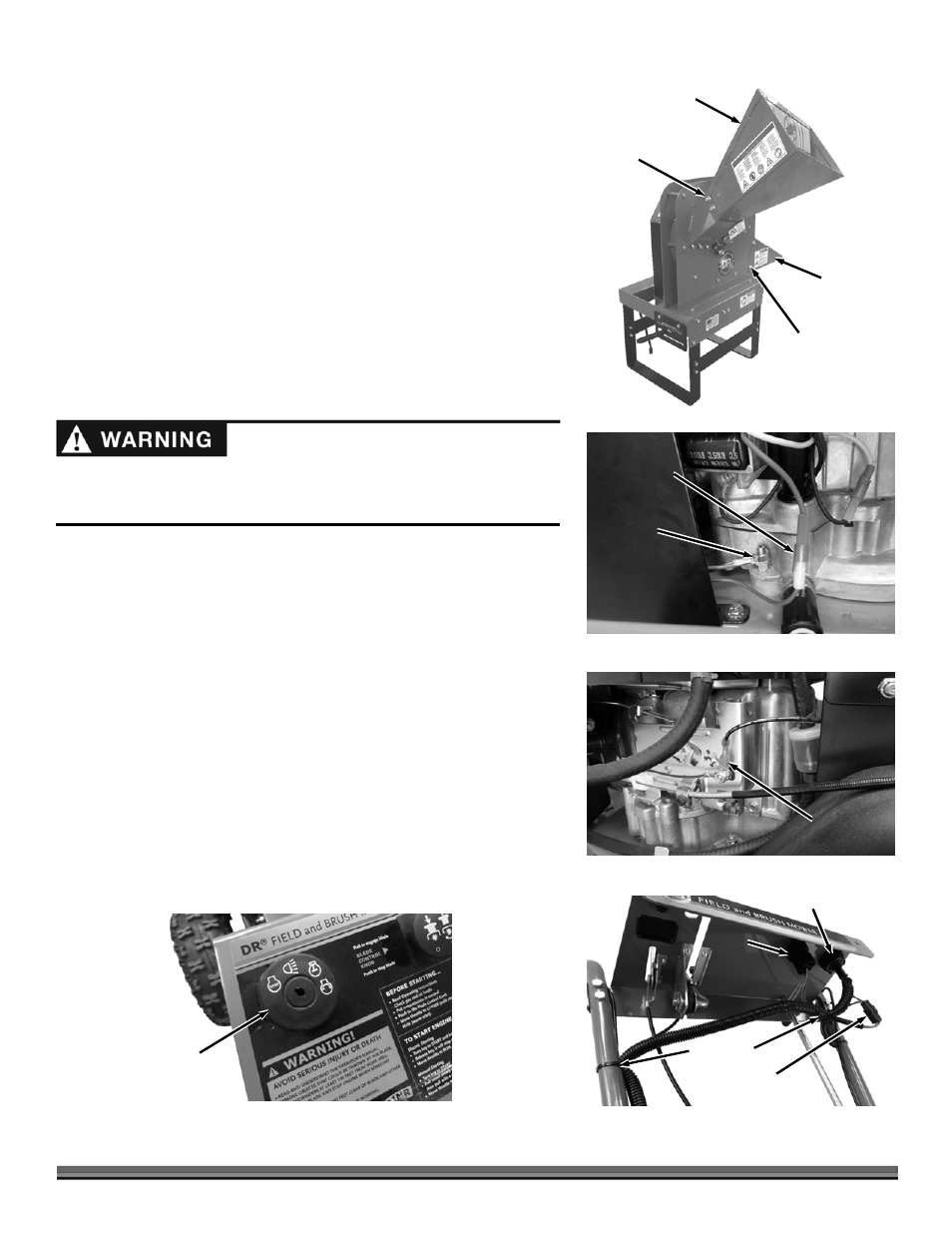
5. Position the Discharge Chute on the side of the chipper and secure with two
Bolts, four Washers (one on each side), and two Locknuts using two 1/2"
wrenches (Figure 8).
NOTE: Ensure that the square in the Carriage Bolts slide fully into the slots in the
Hopper to ensure the bolt heads will rest flush to the Hopper surface.
6. Position the Hopper and secure with four Carriage Bolts (Carriage Bolt Head
inside of Hopper and square of Bolt fully into slots in Hopper), four Washers
and four Locknuts using a 1/2" wrench.
Replacing the Main Field and Brush Mower Harness on machines
with a Briggs and Stratton 12.5 hp Engine (serial numbers from
ATM123741 to ATM126369).
Tools Needed:
1/2" Wrench
9mm Wrench
Wire Cutters
1. Disconnect the Charging Connector from the Engine (Figure 9).
2. Remove the Green Ground Wire from the Engine Mounting Bolt using a
1/2" Wrench.
3. Remove the Engine Kill Wire from the Throttle Linkage using a 9mm Wrench
(Figure 10).
4. Unplug the Blade Control, Key Switch and Operator Presence Connectors
(Figure 11).
5. Cut all Cable Ties that secure the Harness to the machine.
6. Remove the existing Key Switch by pushing in the Tabs underneath and
pulling
it from the
Control Panel
(Figure 12).
7. Install the
new
Key
Switch into
the
Control Panel.
Figure 10
Engine Kill
Connector
Figure 8
Bolt, Washers
and Locknut
Discharge
Chute
Hopper
Carriage
Bolt, Washer
and Locknut
Before performing this Harness change, stop the engine, wait five (5) minutes
to allow all parts to cool. Disconnect the spark plug wires, keeping them away
from the spark plugs.
Ground
Connector
Figure 9
Charging
Connector
Blade
Control
Connector
Figure 11
Key Switch Connector
Operator Presence
Connector
Cable Ties
Key
Switch
Figure 12