DR Power Chipper User Manual
Page 25
CONTACT US AT www.DRpower.com 25
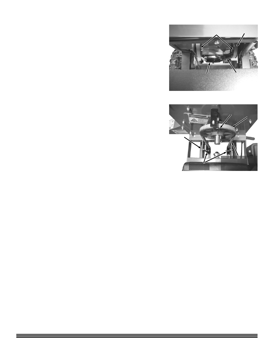
5. Position the Belt onto the Field and Brush Mower Pulley (Figure 47) and then
route it over the two Idler Pulleys and up around the Chipper Pulley (Figure
48).
NOTE: Ensure that the “V” portion of the Belt rests properly into the Idler Pulleys.
6. Move the Belt Release Lever to the “Tighten” position.
NOTE: There is a slot in each of the bottom Tabs of the Belt Guard. These slots must
slide over the Carriage Bolt Guides that are mounted to the inner Frame
Supports of the Chipper (Figure 45).
7. Reinstall the Belt Guard and secure with the Hand Knob.
Belt
Figure 47
Chipper Idler
Pulleys
Field and
Brush Mower
Pulley
Twist Belt to
Engage “V”
Properly into
Idler Pulleys
Belt
Figure 48
Idler Pulleys
Chipper
Sprocket
Twist Belt so “V”
Engages Properly into
Chipper Sprocket
Carriage
Bolt for
belt guard
mounting
(one on
each side)