Installation, Select remote mode on the vtr's front panel, Connection diagram – DNF Controls ST304-Edit User Manual
Page 8: Installation 4, Iii. installation, Iv. connection diagram
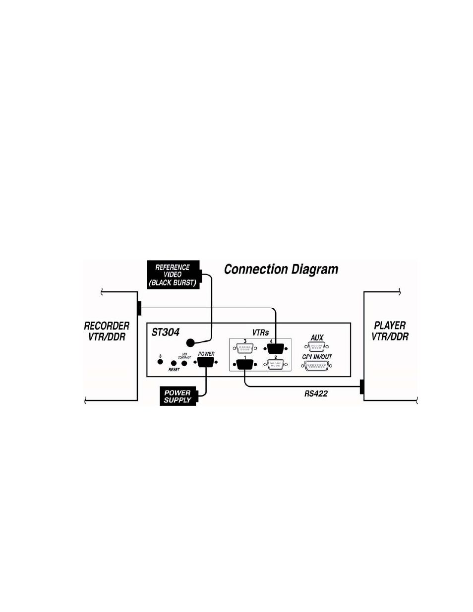
III. INSTALLATION
i)
Plug one end of a 9-conductor, RS422 serial cable into the VTR1, VTR2, VTR3, or
VTR4 connector on the rear of the ST304. Plug the other end of the cable into the 9-pin
REMOTE connector on the VTR.
ii) Connect Black Video to the Reference Video BNC on the rear of the ST304.
iii) NOTE: The ST304 will perform edits without reference. Reference Video is required
for frame accurate edits.
iv) Plug the Power Supply into an outlet, 90 VAC – 240 VAC.
v) Select REMOTE mode on the VTR's front panel.
vi) Check the SETUP MENU prior to using the Slow Motion Controller to confirm proper
Record mode, SLO-MO speed range, and other User settable modes.
IV. Connection diagram
4
S
S
T
T
3
3
0
0
4
4
-
-
E
E
D
D
I
I
T
T
&
&
S
S
T
T
3
3
0
0
4
4
-
-
E
E
D
D
I
I
T
T
-
-
T
T
,
,
S
S
l
l
o
o
w
w
M
M
o
o
t
t
i
i
o
o
n
n
C
C
o
o
n
n
t
t
r
r
o
o
l
l
l
l
e
e
r
r
- 2034CL-N (30 pages)
- 4000CL-O V3.1 (32 pages)
- 2034CL-N-PBIO (33 pages)
- 2034CL-TO (24 pages)
- 4000CL-Q (22 pages)
- 2034CL-TO-PBIO (27 pages)
- 2034CL-SX-PBIO (21 pages)
- 4000CL-SX (26 pages)
- 2034CL-MAV (22 pages)
- 2034CL-MAV-PBIO (23 pages)
- 2034CL-L Vs.3.0 (26 pages)
- 2034CL-L-PBIO VS.3.0 (28 pages)
- 4040CL_(-A, -L, -O, -NX, -7, -8, -T, -P) (43 pages)
- 2044CL-L-8 (27 pages)
- 2MCE (19 pages)
- 3040P-L_&_3040P-L-LT (20 pages)
- 3040P-L_&_3040P-L-LT (27 pages)
- 4000CL-LPH (16 pages)
- 3040P-DLO-L (39 pages)
- 4000CL-L-KBIO Vs.3.0 (21 pages)
- 4000CL-MAV70 (14 pages)
- 4000CL-N (25 pages)
- 4000CL-MAV (18 pages)
- 4000CL-TO (21 pages)
- 4000CL-AX (13 pages)
- 4040CL-EVS-PBIO (26 pages)
- Analyst, RS422/RS232 Tester (35 pages)
- Analyst, RS422/RS232 Tester with (LOG 2) VTR Data Logging Option (31 pages)
- USP3-SBX-VSS (10 pages)
- ST100-CP (6 pages)
- AnyWhere Interface Switch (20 pages)
- ST420-CP (11 pages)
- ST300-CP (13 pages)
- GTP-32 (47 pages)
- ST400-CP (19 pages)
- PBUS G and V Command Addendum (2 pages)
- CP20 (42 pages)
- DC21 (29 pages)
- DMAT-O-22 (27 pages)
- DMAT-EZ (26 pages)
- DMAT-DL (19 pages)
- DMAT-MAV (29 pages)
- DMAT-O-42 (25 pages)
- GC-32 GPIO Controller (14 pages)
- GTP-32BP Installation (2 pages)