Web_delta600th_2700620_rev2_gb.pdf, Characteristics, Installer commissioning installation – Delta Dore PACK DELTA 600 User Manual
Page 3
Characteristics
• Runs on two LR03-type 1.5 V alkaline batteries
(autonomy greater than 1 year)
• Battery level indicator
• Operating mode selector knob (7 positions)
• Choice between 3 continuous temperatures:
Frost protection, Economy, Comfort
and 1 customizable program per day
• The 3 set-point temperatures can be adjusted
from:
5° to 30°C for Economy and Comfort,
5° to 15°C for Frost Protection
• Built-in proportional control (category B), time
basis: 15 min.
• Stand-by mode
• 868 MHz transmission frequency
(300 220 standard)
• Radio range 100 to 300 metres outside
depending on the linked equipment (the range
can be altered depending on the installation
conditions and the electromagnetic environment)
• Addressing: 65536 combinations
• Digital display
• Room unit: 126 x 85 x 31 mm
• Wall-mounted or on base
• Protection index: IP 30
• Class III insulation
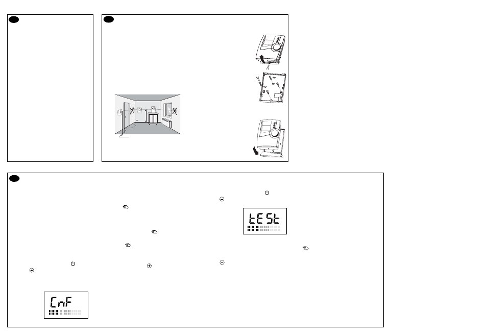
Installer commissioning
Installation
2.1 Positioning options
2.1.1 Radio transmission
The thermostat must be positioned correctly.
In dwellings, the propagation of radio waves is reflected
and attenuated by the structures encountered.
We recommend that you check radio transmission
quality using the radio transmission test mode (§ 3.4).
2.1.2 Measuring temperature
Place the unit in a room whose temperature represents
the mean temperature in your dwelling. The recommended
height is 1.5 m; it should be accessible and away from
heat sources (fireplace, sunlight) and from draughts
(window, door).
If the thermostat is on its foldaway base, it can be used as
a genuine heating remote control and taken with you from
room to room.
Min. 20 cm
1.50 m
1
2
3
➃
On the receiver, press “1...6, COM” repeatedly until
the LED of the relevant channel flashes.
• If the green LED (OK) is flashing slowly,
the receiver channel is not configured.
Press the
button.
The green "OK" LED comes on steady. The receiver
channel is configured.
• If the green LED (OK) is on steady, the receiver
channel is already configured.
To reconfigure it, press the
button for 10 sec.
until the green "OK" LED flashes slowly, then release
it.
Press the
button once again.
The green "OK" LED comes on steady. The receiver
channel is "reconfigured".
→
On the transmitter, press
to exit configuration
mode.
3.1 Fitting batteries
The unit is powered by 2 LR03 or AAA-type 1.5 V
alkaline batteries.
See user guide overleaf (§ 5.1).
3.2 Time setting
See user guide overleaf (§ 5.2).
3.3 Configuration / Reconfiguration
For each receiver output there is a transmitter.
The configuration mode is used to couple the receiver
output with a transmitter (no conflict possible with
other outputs). It is also used to check the radio
transmission.
Associating a receiver output with a transmitter
Turn the knob on the transmitter to the
position.
➀
Press the
button (3 sec.) until CnF is displayed.
The transmitter is sending its information to
the receiver.
3.4 Radio transmission check
On the transmitter, turn the knob to the
position.
➀
Press the
button (~3 sec.)
until the following is displayed:
The transmitter is sending
its information to the
receiver.
➃
Transmission is correct if, on the receiver, the "OK"
LED and “the LED of the relevant channel” flash
together.
→
Press the
button to exit radio transmission test
mode.
3.5 Problems?
On the receiver, a channel's red LED flashes
(the receiver has not received information from
the transmitter of the relevant channel for more
than an hour).
1) Check the transmitter batteries.
2) Go to transmission test mode.
- If the "OK" LED and “the LED of the relevant
channel” are not flashing together each time
information is received, move the transmitter.
- If the problem persists, reconfigure the units.
Note: In the event of malfunction, pressing
the
button on the receiver changes the status
of the selected channel (exemption) until the next
transmission from the thermostat (which continues
to have priority). For an override, the red LED flashes.
2.2 Mounting
2.2.1 Wall-mount (preferred)
To mount the unit on the wall, it
must be separated from its base.
Once separated from the case,
the support must be fixed to the wall
with screws and plugs or on a
flush-mounted box (distance
between centres 60 mm).
2.2.2 Using the foldaway base (option)
Using the support provided,
you can place the transmitter
on an item of furniture or a table,
remembering to adhere to
the conditions for transmission
and thermal location.
DELTA 600 TH
Installation . Installation . Installation . Installation . Installation .Installation . Installation . Installation . Installation . Installation . Installation .