Delta Dore PACK DELTA 600 User Manual
Page 2
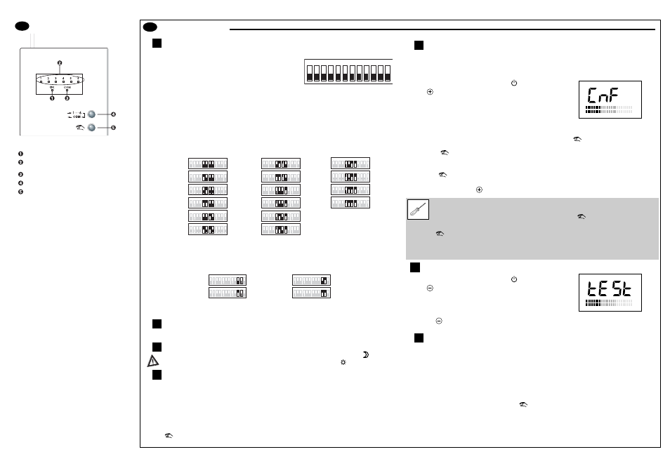
Starting up
Configuring the technical unit outputs
Remove the receiver unit from its base to access the configuration switches.
SW1: Type of relay control (1A outputs)
ON: Normally closed
OFF: Normally open
This selection affects all 6 relay outputs simultaneously.
SW2: Burner or circulator selection (output 5A)
ON: Circulator (activates SW3 function)
OFF: Burner
SW3: Anti-seizing function of the circulator (active if the SW2 selection is ON)
ON: Anti-seizing
OFF: No anti-seizing
SW4: Keep last valve controlled open
(for constant water circulation in the hydraulic circuit).
ON: Keep last valve controlled open
OFF: Authorizes closure of last valve controlled
SW5 to SW8: Solenoid valve opening times
Selection to be made according to the solenoid valves' technical characteristics.
SW9: Control time base
ON: 10 minutes (recommended for air-flow systems)
OFF: 20 minutes (best for hot-water radiant floors)
SW10 to SW11: Limit the cooling operation percentage
Limit according to the installation's cooling over-power.
SSW12: Not used
Technical control unit operation
LThe auxiliary contact is closed when one of the transmitters is in need of heat or cold.
Cooling mode operation (air-flow system)
When change-over is activated (Cooling mode), the Economy set-point temperature
on the thermostats must be higher than the Comfort set-point temperature
.
Radio receiver operation
The 2 Heating and Cooling controls are calculated simultaneously. The LEDs on the receiver unit's front
side allow either Heating or Cooling controls to be viewed.
Selection method: from normal display, press the 2 buttons for 5 sec. (the 6 LEDs flash quickly
indicating "control view selection" mode):
• for heating periods (change-over open), use the browsing button “1...6, COM” to select the red LED
(Com).
The unit displays the Heating control.
• for cooling periods (change-over closed), use the browsing button “1...6, COM” to select the green
LED (OK).
The unit displays the Cooling control.
Use the
button to exit this mode (automatic exit after 2 min. of inactivity).
Radio configuration / reconfiguration
Configuration mode lets you couple a transmitter (Thermostat Delta 600 TH, Delta 600 COM centralized
control) with the Delta 600 BT receiver (no conflict possible with neighbouring installations). It is also used
to check the radio transmission.
➊
On the transmitter, turn the knob to the
position.
➋
Press
(~3 sec.) until CnF is displayed.
The transmitter sends its information to the receiver.
➌
On the receiver, push “1...6, COM” repeatedly until the LED of
the relative channel flashes.
• If the green LED (OK) is on steady, the receiver channel is already configured.
To reconfigure it (with another transmitter, for example), press the
button for 10 sec. until the
green "OK" LED flashes slowly, then release it.
Press the
button again.
The green "OK" LED comes on steady; the receiver channel has been "reconfigured".
• If the green LED (OK) is flashing slowly, the receiver channel is not configured.
Press the
button.
The green "OK" LED comes on steady. The receiver channel is configured.
➍
On the transmitter, press
to exit configuration mode.
Radio transmission check
➊
On the transmitter, turn the knob to the
position.
➋
Press
(~3 sec.) until tESt is displayed.
The transmitter sends its information to the receiver.
➌
Transmission is correct if, on the receiver, the "OK" LED and
“the LED of the relative channel” flash together.
➍
Press the
button to exit the radio transmission test mode.
Problems?
A channel's red LED flashes (the receiver has not received information from the transmitter of the
relevant channel for more than an hour).
1) Check the transmitter batteries.
2) Go to transmission test mode.
- If the "OK" LED and "the LED of the relative channel" are not flashing together each time
information is received, move the transmitter.
- If the problem persists, reconfigure the units.
Note: In the event of malfunction, pressing the
button on the receiver changes the status of the
selected channel (exemption) until the next transmission from the thermostat (which continues to have
priority). For an override, the red LED flashes.
5.7
5.6
5.5
5.4
5.3
5.2
5.1
5
ON
1
2
3
4
5
6
7
8
9
10
11
12
ON
1
2
3
4
5
6
7
8
9
10
11
12
ON
1
2
3
4
5
6
7
8
9
10
11
12
ON
1
2
3
4
5
6
7
8
9
10
11
12
ON
1
2
3
4
5
6
7
8
9
10
11
12
No limit
75% limit
50% limit
25% limit
ON
1
2
3
4
5
6
7
8
9
10
11
12
ON
1
2
3
4
5
6
7
8
9
10
11
12
ON
1
2
3
4
5
6
7
8
9
10
11
12
ON
1
2
3
4
5
6
7
8
9
10
11
12
ON
1
2
3
4
5
6
7
8
9
10
11
12
ON
1
2
3
4
5
6
7
8
9
10
11
12
ON
1
2
3
4
5
6
7
8
9
10
11
12
ON
1
2
3
4
5
6
7
8
9
10
11
12
ON
1
2
3
4
5
6
7
8
9
10
11
12
ON
1
2
3
4
5
6
7
8
9
10
11
12
ON
1
2
3
4
5
6
7
8
9
10
11
12
ON
1
2
3
4
5
6
7
8
9
10
11
12
ON
1
2
3
4
5
6
7
8
9
10
11
12
ON
1
2
3
4
5
6
7
8
9
10
11
12
ON
1
2
3
4
5
6
7
8
9
10
11
12
ON
1
2
3
4
5
6
7
8
9
10
11
12
5
6
7
8
9
10
11
12
Valve opening delay
0 sec.
30 sec.
1min.
1min. 30s.
2min.
2min. sec.
3min.
3min. 30sec.
4min.
4min. 30sec.
5min.
5min. 30sec.
6min.
6min. 30sec.
7min.
7min. 30sec.
Description
The
Delta 600 control receiver is made up of 2
units:
- a receiver unit that receives information from
the transmitters (Delta 600 TH programmable
thermostats, Delta 600 COM centralized
control) by radio waves
- a technical unit, connected to the receiver unit
by a fixed-wire bus, which acts as a power
interface for controlling the installation's
valves.
Delta 600 will manage up to 6 hot-water heating or
air-conditioning outputs.
Delta 600 is designed for:
• hot-water heating (underfloor or radiators)
• air-flow air-conditioning
• cooling floors equipped with dewpoint control
2 operating modes:
• Current mode:
- Channel status display
- Display of the presence or absence of a
centralized control
• Configuration mode:
- Display of whether or not a channel is
configured
- Manual activation of the channels in case of
a fault
Normal operation LED
Control status of the programmable
radio thermostats (Delta 600 TH)
Scrolling button
Configuration button
Presence of the Delta 600 COM control unit
Because of changes in standards and equipment, the characteristics given
in the text and the illustrations of this document are not binding unless
confirmed by Delta Dore.
4
Unconfiguring a channel
➊
To select a channel to unconfigure,
press “1...6, COM” repeatedly on the
receiver until the LED of the relevant
channel flashes.
➋
Hold the
button down until the green "OK"
LED flashes (~30 sec.).
➌
Press the “1...6, COM” repeatedly until you exit
the mode.
Unconfiguring all channels
On the receiver, from the current operating
mode, press the
button and hold it down until
the green "OK" LED flashes (~60 sec.).
The unit is now unconfigured.