Delta Dore 610 RF TYBOX User Manual
Tybox 610 rf, Rf weekly programmable thermostat
PROG
AUTO
TYBOX
0h 2
4
6
8 10 12 14 16 18 20 22 24
1234567
i
PR
OG
AUTO
O
0h 2
4
6
8 10 12 14 16 18 20 22 24
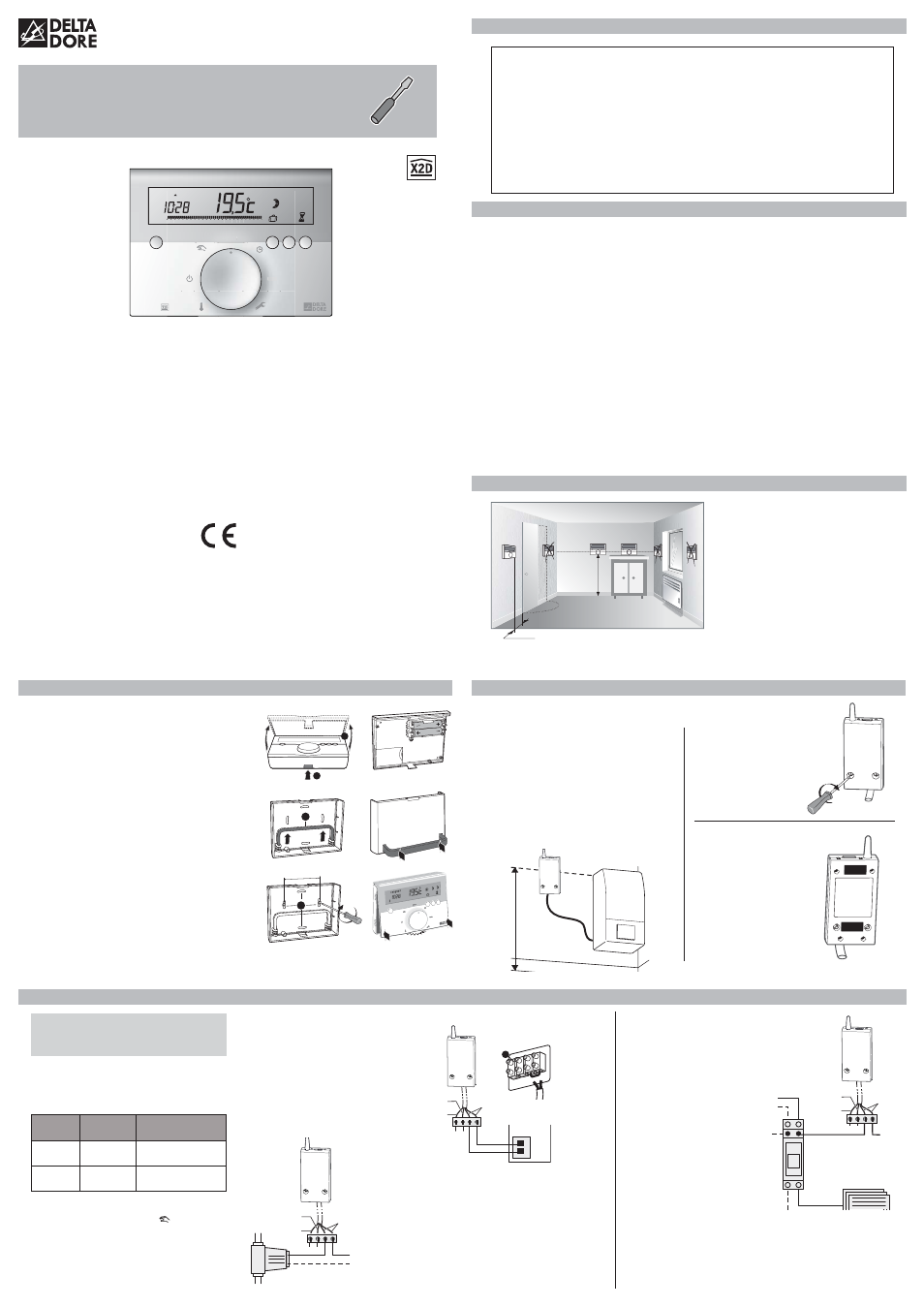
TYBOX 610 RF
RF Weekly programmable thermostat
Installation guide
This appliance is compliant with the requirements of
directives 2004/108/EC (Electromagnetic Compatibility)
and 2006/95/EC (Low-Voltage Safety)
Because of changes in standards and equipment, the characteristics given in the text and the illustrations provided in this
document are not binding unless expressly confirmed
*2702306_Rev.4*
1 - Warnings
3 - Fitting the thermostat
2 - Technical features
Thermostat
• Power supplied by two AAA-type 1.5 V
alkaline batteries (supplied), autonomy
of 2 years for normal use
“No rechargeable batteries”
• Class III insulation
• Wireless remote control device
• Proportional integral regulation
Time base: 15, 30, or 45 minutes
• Radio frequency 868 MHz, class I
(standard EN 300 220)
• Radio range 100 to 300 metres outside, variable
depending on the associated equipment (the
range can be altered depending on the installation
conditions and the electromagnetic environment)
• Mounting with screws or on a support
• Dimensions : 111 x 84 x 28,5 mm
• Protection index: IP 30
• Storage temperature: -10°C à +70°C
• Operating temperature: 0°C à + 40°C
• Installation in an environment with normal
pollution levels
Receiver RF 640:
• 230 V, 50 Hz power supply, ±10%
• Power consumption: 0.5 VA
• Class II insulation
• 1A powered contact outputs, 230V, cos
ϕ = 1
• Type 1.C automatic action (brownout)
(standard EN 60730-1)
• Radio frequency 868 MHz,
(standard EN 300 220)
• Radio range 100 to 300 metres outside, variable
depending on the associated equipment (the
range can be altered depending on the installation
conditions and the electromagnetic environment)
• X2D protocol: the communication language bet-
ween the thermostat and the receiver.
• Operating temperature: 0 à +50°C
• Protection index: IP 44 - IK 04
• Storage temperature: -10 à +70°C
• Dimensions : 82 x 108,5 x 19 mm
• Installation in an environment with normal
pollution levels
4 - Fitting the batteries
To control the heating, the thermostat
must measure the most representative
room temperature in your home. As the
temperature measurement probe is in the
transmitter unit, you must place the unit:
• in the main room (e.g. living/dining room)
or in the middle of your home,
• wall-mounted or placed on a shelf or
accessible furniture at a height of 1.50 m,
• away from heat sources (fireplaces,
sunlight) and draughts (windows, doors),
• on an interior wall.
approx.
1.50 m
Mini 40 cm
• Open the thermostat housing by pressing
on clip
➊
• Remove the plastic tap.
Never use rechargeable batteries.
Use only alkaline batteries.
Fit the transmitter on to its base
• Remove the cover
➌
from its housing
• Position it on the back of the unit
• Reposition the front part of the transmitter
unit until the clip locks into place
Mounting the transmitter on a wall
• Secure the base using the supplied screws and
pegs or fit onto a flush-mounted box (distance
between centres 60 mm) using the knockout
partitions
➍
• Reposition the front part of the transmitter unit
until the clip locks into place
1
3
4
60 mm
2
Click
1
2
3
1
2
3
Location
The receiver must be placed near the
heating control.
To avoid interference with the radio
transmission, the antenna must be free
from any metallic elements (cables,
metallic covers, etc.).
Screw-mounting
Mounted on a wall
using the screws and
pegs supplied.
Mounting by double-
sided adhesive tape
Mounting on the wall
using the double-sided
adhesive tape supplied.
Ensure that the surface
on which the tape is
applied is thoroughly
clean before attaching
the tape.
5 - Receiver location and mounting
Mounting close to a boiler
receiver
Boiler
approx 2 m
from the floor
above the top of the
boiler
Switch off the mains power supply
to your electrical meter (general circuit
breaker) before any intervention.
Inverting the relay contact position
During an On command: the relay closes.
During an Off command: the relay opens.
You can invert the operation of the relay by
pressing the relevant button
on the
receiver for about 10 seconds.
Command
sent
Contact
Inverted contact
ON
ON
OFF
OFF
OFF
ON
Connecting a boiler
with thermostat input
Connecting a boiler
without thermostat input
If the boiler does not have a thermostat
input, you can directly control the circulator
pump located next to the boiler (the pump
enabling circulation of the hot water into
the radiators).
• Directly control the power supply to
the circulator using the receiver.
N
L
230V/50Hz
230V
black and
grey wires
brown wire
blue wire
Circulator pump
6 - Connecting the receiver
N
N
L
L
230V/50Hz
230V
Controlling electric convectors
To control electrical convectors, you MUST
use a power contact switch that is suitable for
the total power to be controlled.
This power
contactor switch
must be fitted into
the electrical
switchboard of
your home.
Configuring and radio testing the receiver
To configure or verify the configuration of the system as well
as the quality of radio transmission, please refer to the CF08
and CF09 configuration menus in this guide.
black and
grey wires
brown wire
blue wire
Power supply
of the contact
switch coil
contact switches (not
supplied) fitted in the
electrical switchboard
convector(s))
• Connect the black wires of the
receiver to both terminals of the
boiler thermostat input.
• If necessary, remove the shunt
(electric wire) connecting the two
thermostat input terminals.
• If the boiler has a clock input,
do not mistake it for the thermostat
input.
... / ...
230 V
5
Remove
the shunt
wires to be
connected to
the receiver
Example of a boiler
terminal box
Boiler
thermostat
input
Boiler
black and
grey wires
brown wire
blue wire
• Carefully read these instructions prior to installation.
• The unit must be installed in compliance with current standards.
• Always switch off the mains before installing or servicing the unit.
• Do not attempt to repair the unit yourself; an after-sales service is available.
• Check that the fastenings are suited to the surface to which the unit will be attached
(plasterboard, brick, etc.).
• The diagrams provided have been simplified for greater clarity. Protections and other
accessories required by standards are not illustrated. The standards and industry best
practices must be complied with. Connected or nearby units must not generate excessive
interference (directive 2004/108/EC).