Maintenance, Photocell problems, Monitor problems – Daktronics C44 User Manual
Page 51: Isolation interface problems
Maintenance &
4-3
Troubleshooting
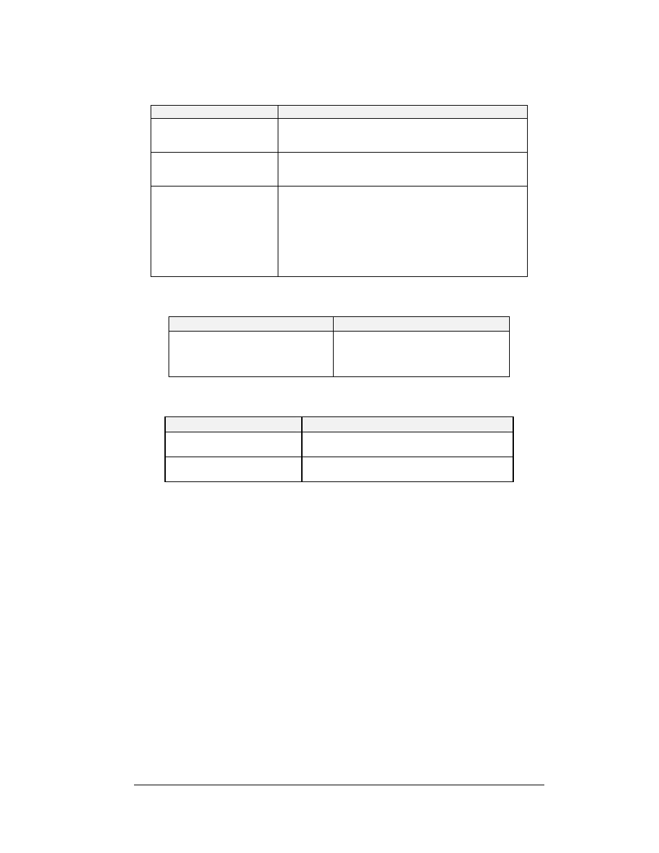
Photocell Problems
Symptom/Condition
Possible Cause/Remedy
All
•
Check power to isolation interface
•
Check field and logic +5V LEDs on isolation
interface
All in one lane
•
Exchange photocell board
•
Swap PC board around to see if problem moves
to other side. (make sure to change dip switches)
Individual
•
Check to see if square lights on the monitor main
screen
•
Check red photocell LED on isolation interface
•
Realign photocell
•
Change photocell
•
Check photocell wiring for shorts or opens
•
Wire any unused photocells together at the
isolation interface.
Monitor Problems
Symptom/Condition
Possible cause/remedy
Nothing appears on monitor
•
Check monitor connection
•
Check power to C-44
•
Depress the reset switch
•
Check video port.
Isolation Interface Problems
Symptom/Condition
Possible cause/remedy
No LED’s lit
•
Check power to isolation interface
•
Check front panel fuse
No photocell LED’s lit
•
+5v field and +5v logic LED’s lit?
•
Check field wiring plugs
4.2
Maintenance
Always disconnect the system when it is not in use. Damage due to power surges and
lightning strikes can be significantly reduced by disconnection and storage of field control
equipment between events. Tower equipment should be powered down and if possible,
removed from signal wiring coming from the field.
Note: If field cabling is to remain connected to the isolation interface when not in use, the
isolation interface should be powered down via the front panel switch and must remain
plugged in to a three-conductor earth grounded outlet (to provide a discharge path to ground
for any voltage surges picked up by field cabling).
To prevent poor electrical contact due to corrosion on field control equipment connectors
(tree, photocells, start line electronics box, etc.), application of a silicon based lubricant
(Daktronics part # LU-1002) to terminals and connector pins is advised.
Tree Maintenance: All the electronics needed to operate the starting tree are located inside
the tree on one or two printed circuit boards. It may be interchanged with one from the spare
parts kit if any troubles occur.
Note: Before opening the tree, make sure that the power cord has been removed from its
outlet.