Time slip printer/printer interface wiring – Daktronics C44 User Manual
Page 24
2-10 New
Track
Installation
TB3-4 Red
J1-1
SIGNAL-P
TB3-5 Black
J1-3
GND
1/8 Mile Right
Lane (660
N)
TB3-6
Beldon 8760
(Dak W-1117)
Shield Not
Connected EARTH
TB9-7 Red
J1-1
SIGNAL-P
TB9-8 Black
J1-3
GND
990
N Left Lane
TB9-9
Beldon 8760
(Dak W-1117)
Shield Not
Connected EARTH
TB3-7 Red
J1-1
SIGNAL-P
TB3-8 Black
J1-3
GND
990
N Right Lane
TB3-9
Beldon 8760
(Dak W-1117)
Shield Not
Connected EARTH
TB10-1 Red
J1-1
SIGNAL-P
TB10-2 Black
J1-3
GND
Start of Speed
Trap #2 Left Lane
(1254
N)***
TB10-3
Beldon 8760
(Dak W-1117)
Shield Not
Connected EARTH
TB4-1 Red
J1-1
SIGNAL-P
TB4-2 Black
J1-3
GND
Start of Speed
Trap #2 Right
Lane (1254
N)***
TB4-3
Beldon 8760
(Dak W-1117)
Shield Not
Connected EARTH
TB10-4 Red
J1-1
SIGNAL-P
TB10-5 Black
J1-3
GND
1/4 Mile Left
Lane (1320
N)
TB10-6
Beldon 8760
(Dak W-1117)
Shield Not
Connected EARTH
TB4-4 Red
J1-1
SIGNAL-P
TB4-5 Black
J1-3
GND
1/4 Mile Right
Lane (1320
N)
TB4-6
Beldon 8760
(Dak W-1117)
Shield Not
Connected EARTH
*Isolation Interface
**Intermediate/ Finish Line Photocell J-Box
*** Based on a 66 Ft Speed Trap
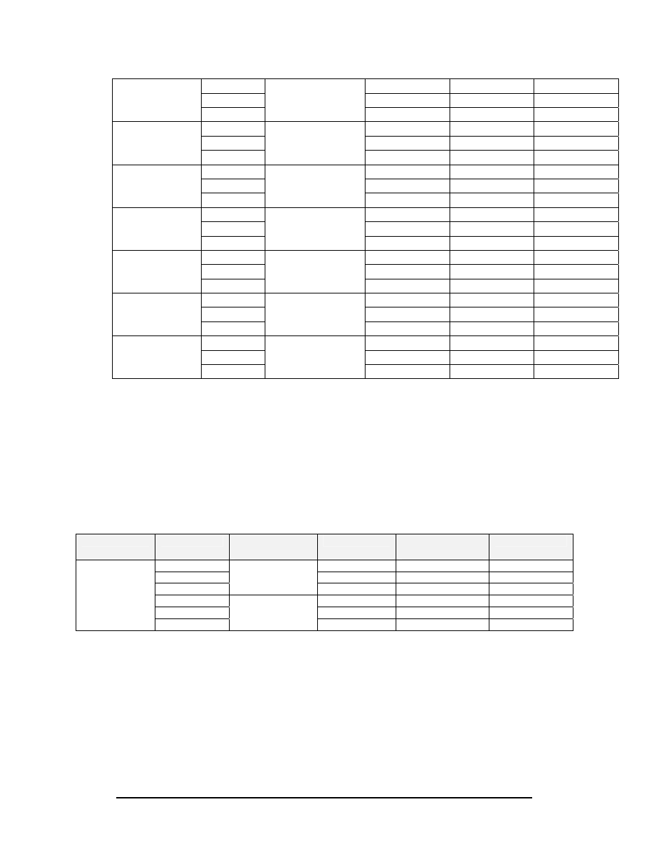
Time Slip Printer/Printer Interface Wiring
The Time Slip Printer is a 40 column Epson TM-4200 or an Epson LX300 (contact
Daktronics for other choices or models). The Time Slip Printer is then plugged into a
Printer Interface. The printer interface has a terminal block (TB1) to connect to the cable
coming from the isolation interface. Refer to the following table for connecting the cable
to the isolation interface. Use two, shielded 18 awg pair cables. You may also reference
the field cabling diagrams (Drawings B-91012 and B-114631).
Description
From (I/I)*
Cable
Specification
Wire Color
To (Printer
Interface)
Function
TB14-1 Red
TB1-4
ETFAULT-P
TB14-2 Black
TB1-5
ETFAULT-N
TB14-3
Beldon 8760
(Dak W-1117)
Shield Not
Connected Earth
TB14-4 Red
TB1-1
ETDATA-P
TB14-5 Black
TB1-2
ETDATA-N
Time Slip
Printer
TB14-6
Beldon 8760
(Dak W-1117)
Shield Not
Connected Earth
*Isolation Interface
Optional: Wiring Between the Isolation Interface and Scoreboards
Wiring between the isolation interface and the scoreboards/dial-in displays use multiple
one pair 18 awg shielded cables. Refer to the following wire connection table to assist in
the installation. You may also reference the field cabling diagrams (Drawings B-91012
and B-114631).