Grounding, 2 lightning protection, 3 fiber conversion box connections – Daktronics Sportsound 500HD User Manual
Page 17: Lightning protection, Fiber conversion box connections, On 4.3
Electrical Installation
11
Grounding
The sound cabinet must be grounded according to the provisions outlined in Article 250 and
600 of the National Electrical Code and according to the specifications in this manual or the
warranty will be void. Proper grounding is necessary for reliable equipment operation and
protects the equipment from damaging destructive disturbances and lightning.
Daktronics recommends a resistance-to-ground of 10 ohms or less. The electrical contractor
performing the electrical installation can verify ground resistance. Daktronics Sales and
Service personnel can also provide this service. The sound system must be earth-ground.
The material for an earth-ground electrode differs from region to region and may vary
according to conditions present at the site. Consult local and national electrical codes.
Daktronics does not recommend using the support structure as an earth-ground electrode;
concrete, primer, corrosion, and other factors make the support structure a poor ground.
Note: The support structure may be used as an earth-ground electrode only if designed to
do so. A qualified inspector must approve the support structure and grounding methods.
4.2 Lightning Protection
The use of a disconnect near the system to completely cut all current-carrying lines
significantly protects the circuits against lightning damage. In order for this device to provide
protection, the power must be disconnected when the system is not in use.
4.3 Fiber Conversion Box Connections
Important Notes:
The fiber box shall not be exposed to dripping or splashing, and no objects filled with
liquid shall be placed on the fiber box.
The fiber box consists of Class 1 construction and shall be connected to a mains
socket outlet with a protective earth-ground connection.
The fiber box utilizes a power cord with wiring inlet as a means for disconnection
from power. This means of disconnection shall remain readily operable in all cases.
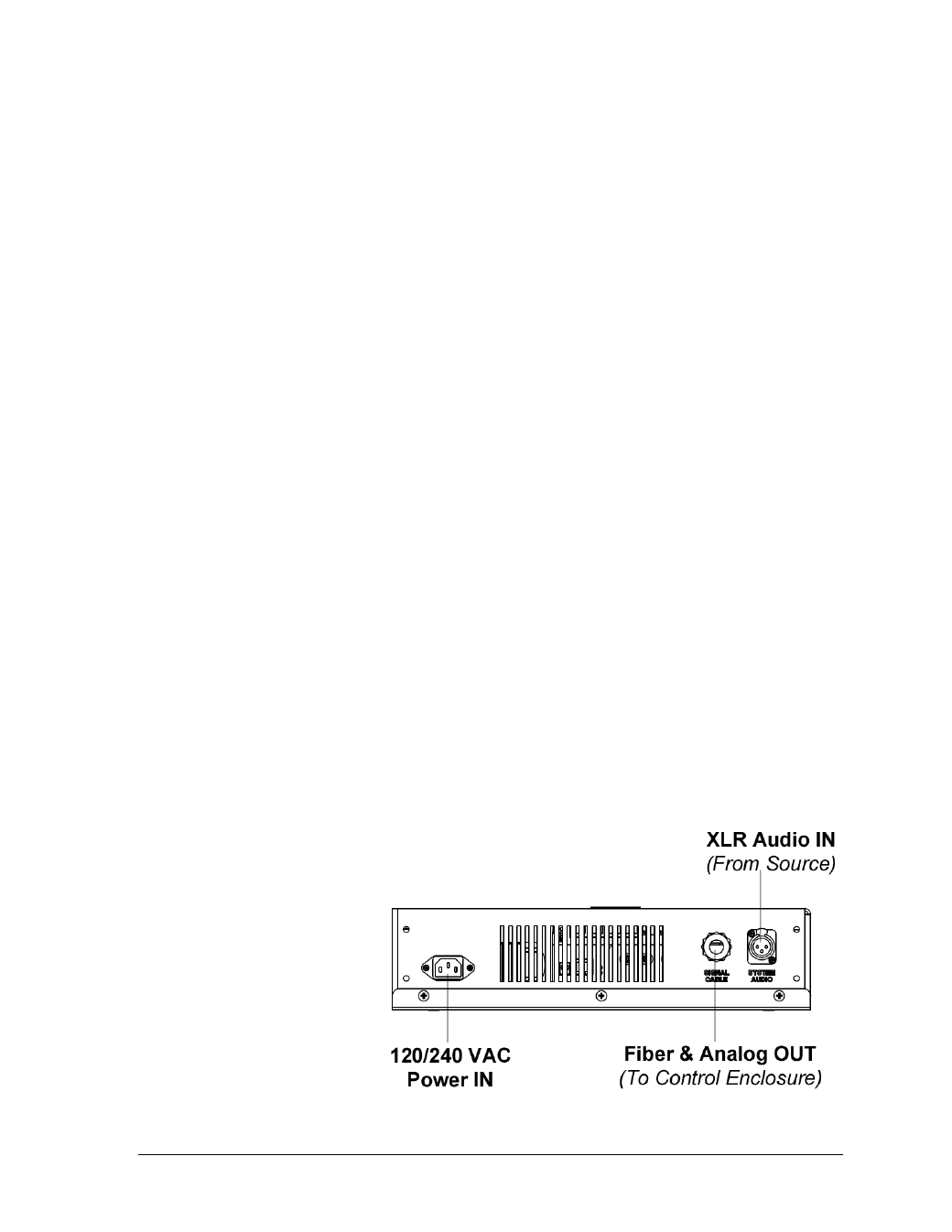
Refer to Figure 15 for
external fiber conversion
box connections and
Figure 16 for internal
connections and
component locations.
Refer to Detail “C” in
Drawing C-980598 for
analog backup
connection and Detail
“D” for fiber connection.
Drawing A-1095894
provides a detailed
wiring schematic.
Figure 15: External Fiber Conversion Box Connections