Power, Signal in, Signal out – Daktronics Sportsound 500HD User Manual
Page 16
10
Electrical Installation
Power
The system requires one (1) 20 amp, 120 VAC, 60 Hz circuit; 2W + GND (or 208/230/240
VAC, 50 Hz for connection to international voltages). Power wiring must be run in conduit
up into the bottom of the control enclosure and terminated at TBL1. Refer to Detail “A” of
Drawing C-980598.
Signal IN
Six-core, multimode 50-micron fiber optic cable (Daktronics part # W-1489) must be run in
conduit from the fiber conversion box location to the sound cabinet control enclosure (FPP2).
Refer to Detail “D” of Drawing C-980598. If included with a Daktronics scoreboard or
display, the sound system may instead use 12-core (part # W-1490) fiber optic cable.
For the analog backup signal, 1 pair, 22 AWG cable (part # W-1615) must also be run in
conduit from the fiber conversion box location to the control enclosure. The cable is
terminated to TRX1. Refer to Detail “E” of Drawing C-980598.
Signal OUT
IMPORTANT: Improper wiring will result in damage to the internal circuitry of the
product, and pose a potential fire hazard!
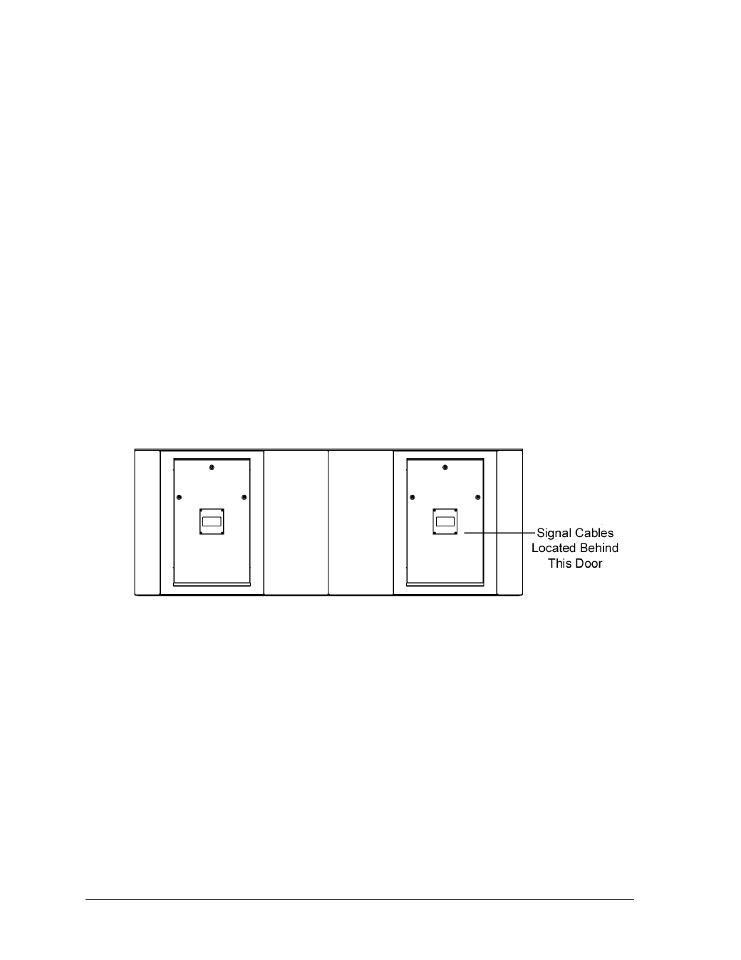
1. Open the far right rear access door (Figure 14) of the sound cabinet. Turn all latches
a
1
/
4
turn using a flathead screwdriver (older latches can be turned with fingers).
Tilt the top of the door away from the cabinet. With the door tilted, use the handle to
lift it up and out of the doorframe.
2. Inside the sound cabinet is a coiled 50' (15.2 m) signal cable. Run this cable in conduit
out the bottom of the sound cabinet, up into the bottom of the control enclosure.
3. Connect each speaker cable to its designated terminal on TBL2, noting the proper
polarity when wiring them. Confirm the proper connections by referring to Detail
“A” of Drawing C-980598.
Note: To prevent the possibility of short circuits, strip each wire 8 mm and tighten
the screw connection terminal to a minimum torque of 0.6 Nm.
Figure 14: Sound Cabinet Access Doors, Rear View