Mounting the cabinet – Daktronics Sportsound 500HD User Manual
Page 12
6
Mechanical Installation
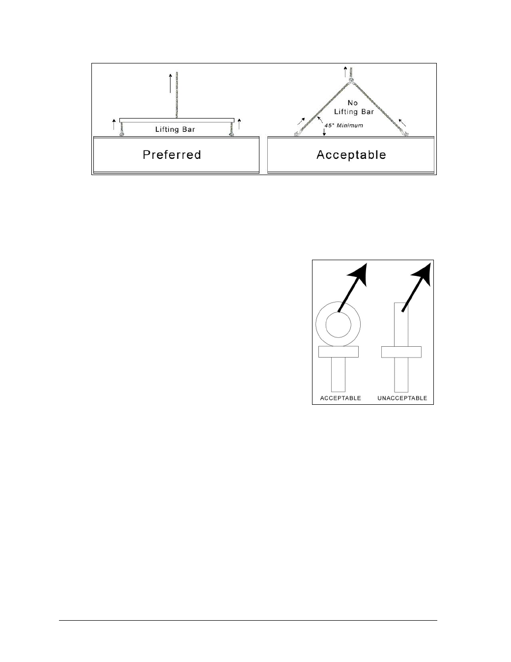
Cables and chains attached to the eyebolts and directly to a center lifting point, as shown in
the right-hand example in Figure 11, can create a dangerous lateral force on the eyebolts and
may cause the eyebolts to fail. The smaller the angle between the cable and the top of the
cabinet, the lighter the sign must be to safely lift it. If this method must be used, ensure a
minimum angle between the chain and cabinet of at least 45°.
Do NOT attempt to lift the cabinet if the angle is less than
45 degrees. Exceeding load angles or weight limits could
cause the bolts in the cabinet to buckle, resulting in
serious damage to the equipment or injury to personnel.
Also, loads should be applied directly in the plane of the
eyebolt as shown in Figure 12.
Note: Daktronics assumes no liability for damages
resulting from incorrect setup or lifting methods.
Eyebolts are intended for lifting only. Do not attempt
to permanently support the cabinet with the eyebolts
or eyebolt holes.
If installers remove the eyebolts, use
1
/
2
" bolts to plug
the holes.
Mounting the Cabinet
Reference Drawings:
SS500HD Mounting; w/ Stringer Mounted Displays .............................. Drawing B-992093
Engineering Specification; Sportsound 500HD ..................................... Drawing B-969776
Side Panel Mounting Details w/ SS500HD ............................................ Drawing B-992088
SS500HD Mounting w/ Pole Clamp Displays ........................................ Drawing C-982267
Single Column Install Specs; SS500HD .............................................. Drawing C-1005534
The sound cabinet will be mounted atop a frame that must be certified by a structural
engineer. To mount the system in place, position the cabinet on the structure where it is to be
mounted. Several mounting methods are available. Weld the cabinet’s bottom members to
the structure at the locations indicated on the appropriate drawing listed above.
Figure 11: Lifting Methods
Figure 12: Eyebolt Plane Load