Main disconnect, Signal termination from computer to sign, Rs/232 – Daktronics AF-3180-64-R,A User Manual
Page 28: Main disconnect -8, Signal termination from computer to sign -8, Rs/232 -8, Figure 23: signal termination, 7 main disconnect, 8 signal termination from computer to sign
3.7 Main
Disconnect
The National Electrical Code requires the use of a lockable power disconnect near
the sign. Provide a lockable disconnect switch (knife switch) at the sign location so
that all power lines can be completely disconnected. Use a 3-conductor disconnect to
disconnect both hot lines and the neutral. Mount the main disconnect at or near the
point of power supply connection to the sign. Provide a main disconnect for each
supply circuit to the sign.
You must locate the means of disconnection in a direct line of sight from the sign or
outline lighting that it controls. This requirement provides protection by enabling a
worker to keep the disconnecting means within view while working on the sign.
Exception: You may locate the disconnecting means that are capable of being
locked in the open position elsewhere.
3.8 Signal Termination from Computer to Sign
Note: The AF-3180 is designed for quicker connection to other displays and other
additional equipment. Connection of the control computer to the first display needs
to be wired to the surge suppressor, modem, or fiberboard in that display. The
following cables are provided with the displays:
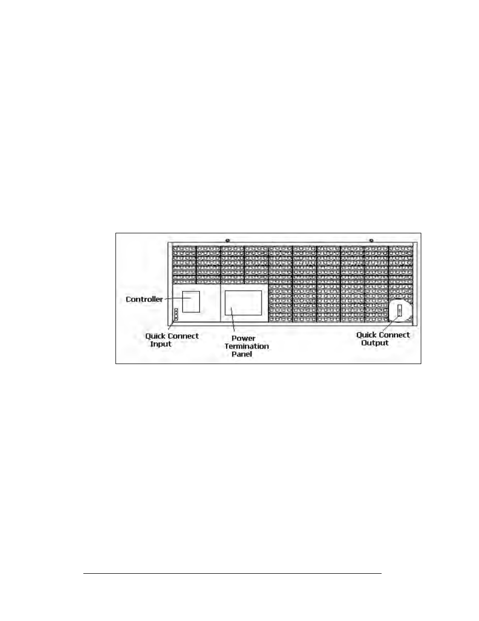
Figure 23: Signal Termination
1. Interconnect cable from Display 1 to Display 2, length 10 feet.
2. Temperature sensor with Quick Connect cable, length 10 feet.
3. Client radio with Quick Connect cable, length 25 feet.
RS/232
Reference Drawings:
System Riser Diagram, RS232 ................................... Drawing A-174341
Schem, Sig Wiring, Internal, W/quick Connect PCB ... Drawing B-177662
Cntrlr; Galaxy, 8 Conn, J1087 ..................................... Drawing B-177838
A display that is controlled using RS232 requires the use of a J-box within 25 feet of
the display. From the J-box to the display, the signal may be connected using a quick
connect cable or directly wired to the controller inside the display. The cable from
the J-box to the display must be routed though conduit. Do not run signal and display
power through the same conduit.
Electrical Installation
3-8