Modem, Fiber optic, Radio – Daktronics AF-3180-64-R,A User Manual
Page 23: Rj connector cables, Modem -3, Fiber optic -3, Radio -3, Rj connector cables -3, Figure 17: 6-conductor rj11 connector and cable, 3 rj connector cables
With interface signals (such as power conductors, intercom, etc.), typically a two-
foot separation is required. The maximum length of an RS422 signal cable is 4,000
feet (1.22 km).
Modem
The modem option will use standard telephone cable routed through conduit. The
local telephone company will need to assist in this installation.
Ask the telephone company which colors are used by the TIP and the RING for
signal hook-up.
Note: The telephone line must be a dedicated line and not run through a switchboard
system.
Fiber Optic
This cable is a 4-fiber cable (Daktronics part number W-1376). Two fibers are used
for display communications and the other two are saved for spares. The cable may be
either direct burial or routed in conduit but should not be subjected to mechanical
flexing. The maximum length of a fiber optic cable is 2,000 feet (611.6 meters).
Radio
The Server radio connected to the computer requires one six-conductor 18 AWG
cable (W-1370) for the signal and the power. This cable needs to be in conduit when
exposed to outdoor conditions. The maximum distance from the J-box to the Server
radio is 1000 feet (304.6 meters).
The Client radio at the display comes with a quick connect cable that is rated for
outdoor use and does not need to be in conduit.
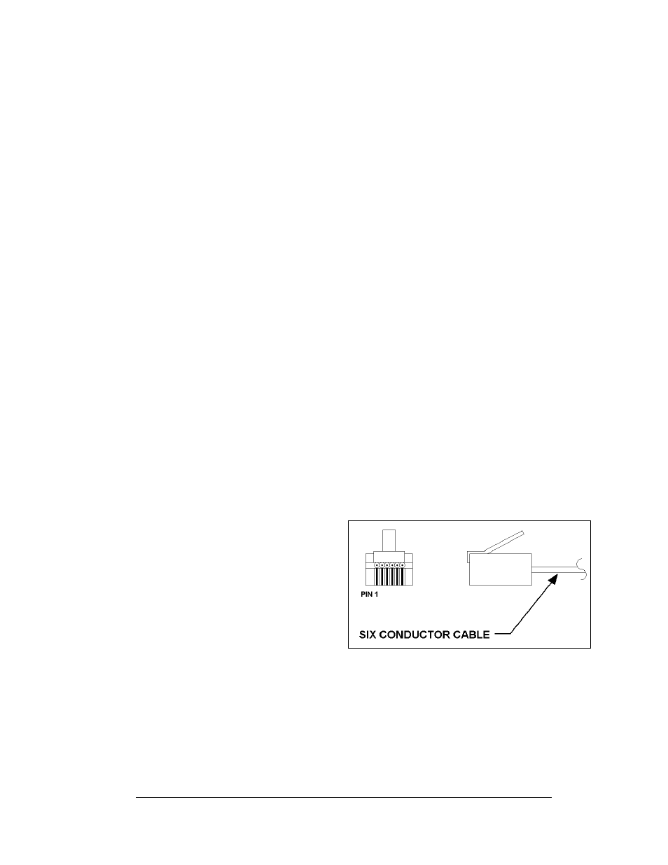
3.3 RJ Connector Cables
The connector used for RS/232 input
to the display is an industry
standard, 6-pin RJ11. This connector
can be found on many telephones
and LANs.
Electrical Installation
3-3
The cable used in the network is a
standard flat six-conductor
telephone cable (standard flipped
cable). Refer to Figure 16 on the
right. This cable has one end that is
the mirror image of the other end
(i.e. the cable is flipped). Refer to Figure 17 below for a standard flipped cable.
Figure 17: 6-Conductor RJ11 Connector and Cable
Notice in Figure 18 that the color code on one connector must be made the opposite
on the other connector. When installing a network, it is not easy to remember in
which direction the previous end was oriented. One simple way to avoid confusion is
to standardize the color code, having one color for the connector going into the
output of a display and the opposite color for a connector going into the input of a
sign. This will help ensure correct cabling since cables are always installed from the
output jack of one sign to the input jack of the next sign.