Rs422 surge suppressor, Rs422 surge suppressor -10, Figure 42: surge suppressor, rs422 – Daktronics AF-3150-20-R,A User Manual
Page 48
The fiber module has three LEDs.
1. The power LED (DS1) should remain lit while power is applied to the
board.
2.
The receive LED (DS2) will flash when the display fiberboard is accepting
signals from the signal converter.
3.
The transmit LED (DS3) will flash when the display fiberboard is sending
signals to the signal converter.
In addition, the fiber module has several input and output jacks:
1. J6 is the power input for 12VAC.
2. J5 and J4 are the inputs from the signal converter by the computer, or the
previous display connects.
3.
J3 and J2 are the outputs to the fiberboard in the next display, if necessary.
4.
J7 is the RS232 output that connects to the J3 on the controller board via an
8-conductor, RJ45 cable (Daktronics part number 0A-1229-0054).
5.
J1 is used when the fiberboard is mounted in an enclosure.
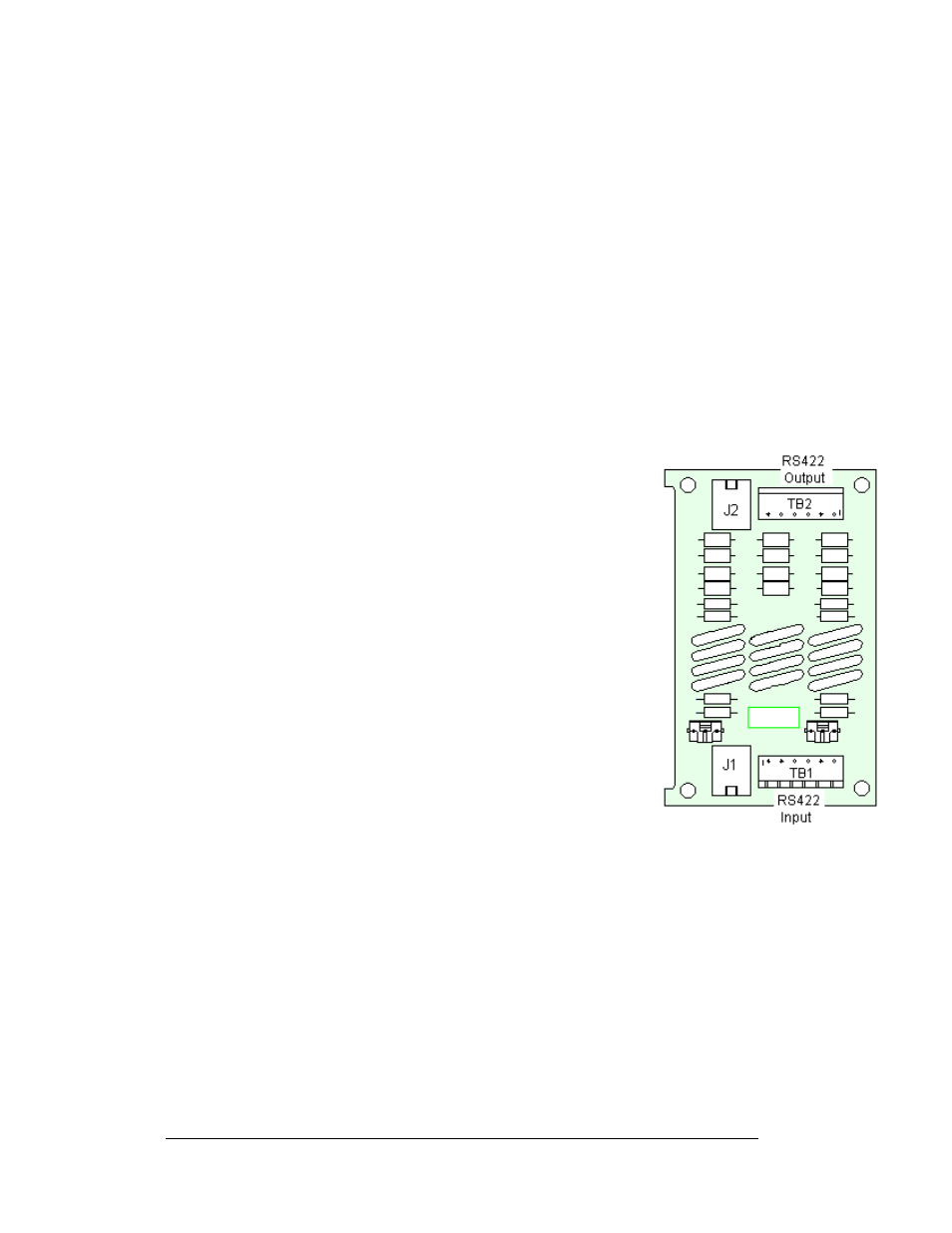
Figure 42: Surge Suppressor, RS422
RS422 Surge Suppressor
The surge suppressor is an inline device that is used to filter
the RS422 data line. It suppresses surges down to a low
voltage in order to protect the display controller’s RS422
input. If a fiberboard was included with the display, it is
located inside the display next to the controller board.
To replace the RS422 Surge suppressor board: Tools
required: 1/8" hex wrench and 3/16" nut driver
1. Remove the module directly in front of the surge
board.
2. Disconnect and label the signal connections (Refer
to
on the right).
3. The surge suppressor is held in place with four
3/16" screws. Carefully remove them.
4. Install the new surge suppressor, replace the screws,
and reconnect power and signal cables.
The surge suppression board has two inputs and two outputs.
1. The cable from the signal converter by the display
will connect to TB1.
2. The signal from the RS422 output (TB2) on the surge board connects to the
RS422 input (TB2) on the controller.
3. J2 will used to connect to the controller board when the surge board is
mounted in an enclosure.
4. J1 and J2 are more often used when the board is part of an indoor display
application.
Note: The surge suppressor must be firmly connected to the display chassis in order
to be effective. The mounting hardware used to secure the surge suppressor is
sufficient if it is fastened properly.
Maintenance and Troubleshooting
4-10