Fiber board, Fiber board -9, Figure 40: modem jumper location – Daktronics AF-3150-20-R,A User Manual
Page 47: Figure 41: fiber optic board
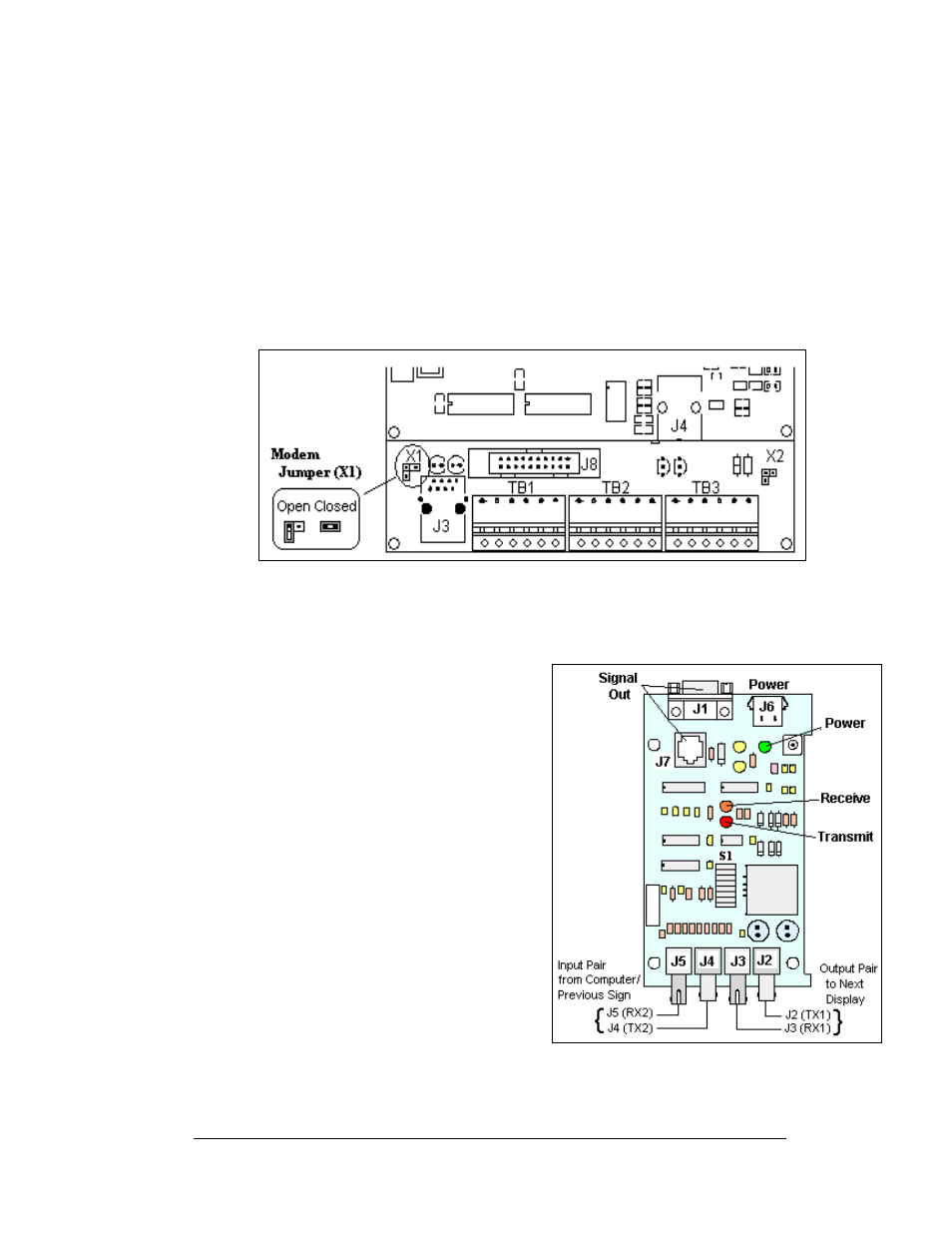
The modem board also has several input and output jacks:
1. J3 is the power input for 12 VAC
2. TB2 is a phoenix connector to terminate the Tip and Ring wires
3. J5 is an RJ11 jack for termination of a pre-terminated phone line
4. J6 is the RS232, RJ45 output to the controller
5. J2, TB1, and TB3 are not used in this display application
A modem system requires a jumper (X1) to be set on the controller board. For a
modem system the jumper must jump both pins. The jumper position is only
recognized on power-up. Refer to the
below for the location, and the
jumper settings.
Figure 40: Modem Jumper Location
Fiber Board
If a fiberboard was included with the display,
it is located inside the display next to the
controller board.
Figure 41: Fiber Optic Board
Complete the following steps to replace a
fiber optic board: Tools required: 1/8" hex
wrench and 3/16" nut driver
1. Remove the module directly in front
of the modem.
2. Disconnect and label the power and
Figure
41
on the right for disconnection of
wires).
3. The fiber optic board is held in
place with four 3/16" screws.
Carefully remove them.
4. Install the new fiberboard, replace
the screws, and reconnect power and
signal cables.
Maintenance and Troubleshooting
4-9