Fiber optic, Fiber optic -14, Figure 29: fiber optic display controller – Daktronics AF-3150-20-R,A User Manual
Page 34
Fiber Optic
Reference Drawings:
System Riser Diagram Fiber ....................................... Drawing A-174344
Schematic, Internal, W/Quick Connect........................ Drawing B-177662
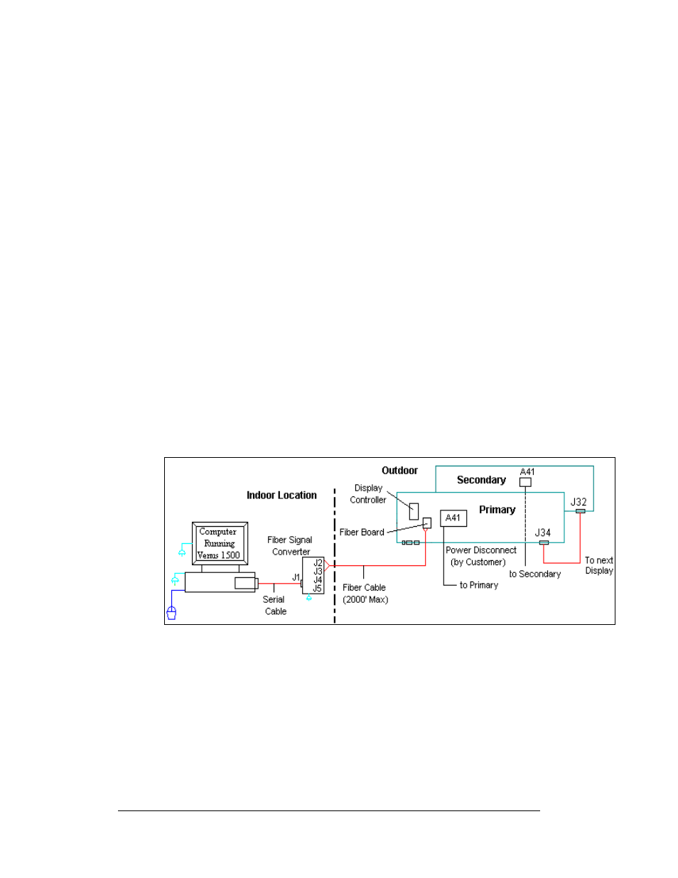
A fiber-controlled display requires the use of a signal converter near the computer.
From the signal converter, cables are run to the fiberboard in the display or in a
junction box. The fiber cables from the signal converter to the display can be routed
through conduit. In the case of fiber only, signal and display power can be run
through the same conduit. Refer to
and Drawing 174344 for the system
layout.
1. If using a junction box with a quick connect cable, connect the two fiber
cables from the signal converter (either J2 and J3, or J4 and J5) to J5 and J4
on the fiberboard. The quick connect cable will connect to the RS232 top
jack (J33) on the back of the primary display.
2. When connecting directly to the fiberboard in the display, route the cable to
the fiberboard and connect the two fibers to J5 and J4. Always connect
transmit (TX) at the signal converter to receive (RX) on the display’s
fiberboard, and RX to TX as shown in
and Drawing B-177662.
3. The fiberboard in the display, connects to the display’s controller via an 8-
pin RJ45 cable (Daktronics part number 0A-1229-0054) from J7 on the
fiberboard to J3 (RS232 IN) on the controller.
4. The computer connects to the signal converter using a DB9 to DB25 serial
cable.
Figure 29: Fiber Optic Display Controller
Electrical Installation
3-14