Installing an rj connector, Conduit, Installing an rj connector -4 – Daktronics AF-3150-20-R,A User Manual
Page 24: Conduit -4, Figure 16: flipped cable with rj connectors, Figure 17: wire with outer jacket stripped, 4 conduit
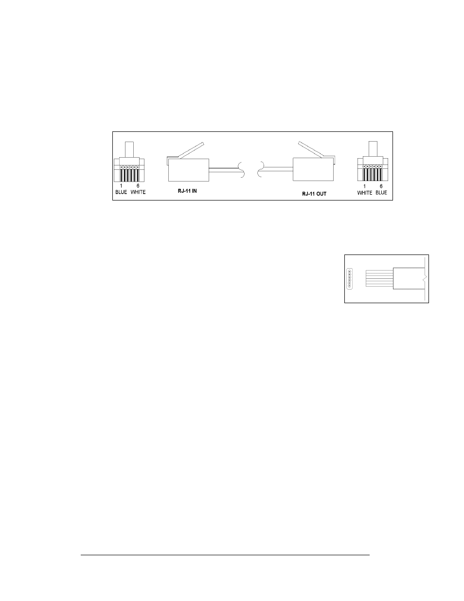
that the color code on one connector must be made the
opposite on the other connector. When installing a network, it is not easy to
remember in which direction the previous end was oriented. One simple way to
avoid confusion is to standardize the color code, having one color for the connector
going into the output of a sign, and the opposite color for a connector going into the
input of a sign. This will help ensure correct cabling since cables are always installed
from the output jack of one sign to the input jack of the next sign.
Figure 16: Flipped Cable with RJ Connectors
Installing an RJ Connector
Installing an RJ connector on the end of the conductor cable is a simple task when
the correct tools are used. The RJ crimping tool (Daktronics part number
TH-1033) performs two separate steps.
Electrical Installation
3-4
First, use the crimping tool to strip the outer insulation from the inner
wires. This does not result in bare wires since only the gray outer jacket is
removed. After correct stripping, the wire will appear as shown in
Figure
17
on the right.
The crimping tool is then used to crimp the RJ connector onto the cable.
The RJ connector is locked into a special socket in the tool. The stripped
wire is inserted into the RJ connector. Finally, the tool is squeezed like a pliers to
crimp the connector onto the wire. This completes the installation of an RJ connector
onto the wire.
Figure 17: Wire with Outer
Jacket Stripped
3.4 Conduit
Reference Drawings:
Shop Drawing; AF-3150-**x**-20mm-R or A............... Drawing B-183660
Daktronics does not include the conduit. Refer to Drawing B-183660 for your
display size and approximate locations for power and signal conduit. Separate
conduit must be used to route:
•
Power
•
Signal IN wires
•
Signal OUT wires (if signal is required for another display)
Knockout holes for ½" conduit are located at the bottom right (rear view) of the back
of the display (refer to Drawing B-183660).
For displays with more than one face, signal and temperature sensor wiring between
displays is normally done using the quick connect interconnect cable, which does not
need to be in conduit. When not using the quick connect cable, the cables for signal
and temperature can be routed through the same conduit.