Modules and drivers, Figure 37: removing a module – Daktronics AF-3150-20-R,A User Manual
Page 45
duplex.
DS10 Red
Collision
Flashes
when
the Ethernet interface detects a
collision in half-duplex.
DS11
Red
+5V
On when +5V power supply is functioning.
DS12
Red
+3.3V
On when +3.3V power supply is functioning.
DS13
Red
+2.5V
On when +2.5V power supply is functioning.
Product Board
LED Color
Function
Operation
DS1
Green
+5V
On when +5V power supply is functioning.
DS2
Green
+3.3V
On when +3.3V power supply is functioning.
DS3
Yellow
COM1 TxD
Flashes when transmitting serial information.
DS4
Yellow
COM1 RxD
Flashes when receiving serial information.
Temp/Light Sensor
LED Color
Function
Operation
DS1
Green
+5V
On when +5V power supply is functioning.
DS2
Red
Run
A steady flash indicates the controller is running
correctly. Normal flash rate is about once a
second. Flashes faster when the sensor is
transmitting temp or light information.
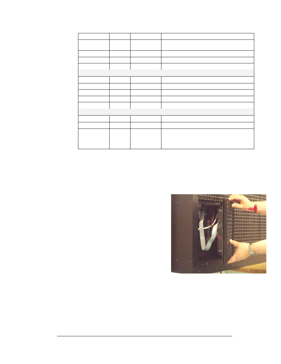
Modules and Drivers
The module and driver board are a single functional unit.
To remove a module, complete the following steps:
Tools required: 1/8" hex wrench
1. Locate the latch access fasteners on the
module. One is centered below the
second row of pixels and one is centered
above the bottom row.
Maintenance and Troubleshooting
4-7
2. With a 1/8"hex wrench, turn the latch
access fasteners a quarter turn as seen in
. The top one should be turned
clockwise and the bottom one counter-
clockwise.
3. Pull the display module far enough to
reach around the back and disconnect the
ribbon and power cables.
When installing a module, reverse the previous
steps and take note of the following points:
•
The weather-stripping on the back edge
of the module must be intact and in good condition if it is to prevent water
from seeping into the display.
Figure 38: Removing a Module
•
The module latches must be fully engaged to create a watertight seal around
the edge of the module. The module should be firmly seated against the
display when the latches are fully engaged.
Each module assembly is made up of a module housing (containing LEDs and the
driver) and a louver assembly.