Section 1: introduction – Daktronics Data Time Series 50 Time & Temperature Displays User Manual
Page 9
Introduction
1-1
SECTION 1 : Introduction
1.1
How To Use This Manual
This manual explains the installation, operation and maintenance of Daktronics Data Time
Series 50 Incandescent Time and Temperature Displays. It provides dimensions and guides
you in mounting, wiring and operating these displays. The manual is divided into mechanical,
electrical, operation and maintenance sections.
For additional questions regarding the safety, installation, operation or service of these displays,
please refer to the phone numbers listed on the cover page of this manual.
K
Important Safeguards:
1. Read and understand these instructions before installing.
2. Do not drop the control console or allow it to get wet.
3. Be sure the display is properly grounded.
4. Disconnect power to the displays when they are not in use.
5. Disconnect power when servicing the displays.
6. Do not modify the displays or attach any panels or coverings to the displays
without the written consent of Daktronics, Inc.
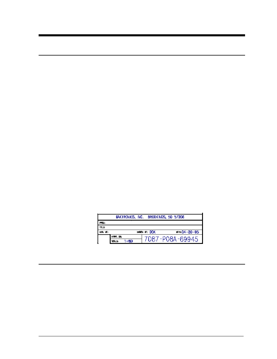
The box below is an illustration of Daktronics drawing numbering system. The drawing
number “7087-P08A-69945” is how Daktronics identifies individual drawings. This number is
located in the lower right corner of the drawing. The manual refers to drawings by the last
five digits and the letter preceding them. In the example below, the drawing would be referred
to as Drawing A-69945. Each set of reference drawings will be inserted at the end of the
section which first references them.
1.2
Display Overview
Reference Drawings:
Shop Drawing, S50-12-SF/2V.............Drawing A-61929
Shop Drawing, S50-18-SF/2V.............Drawing A-56629
Shop Drawing, S50-24-SF-2V ............Drawing A-57794
Shop Drawing, S50-36-SF/2V.............Drawing A-59698
Shop Drawing, S50-48-SF..................Drawing A-58669
Shop Drawing, S50-60-SF..................Drawing A-63117
Refer to the following drawings for overall display specifications for single face and 2V
displays, and mounting details. Also use these drawings as an aid for mechanical installation,
electrical installation and maintenance.