Daktronics Data Time Series 50 Time & Temperature Displays User Manual
Page 75
Appendix D: Update Triac
Time & Temperature
D-3
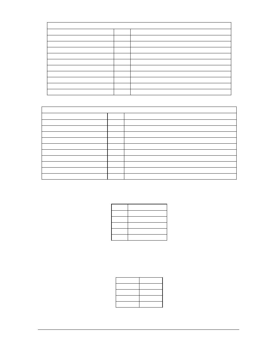
Digit 3
Driver Designation/Color
TB3 Lampbank Designation (Existing)/Color
F43 RED
1
Common WHT/VIO, WHT/GRY (2 Wires)
NC
2
NC
J11-3 BRN
3
Seg. A WHT/BLK/BRN
J11-2 RED
4
Seg. B WHT/BLK/RED
J11-1 ORN
5
Seg. C WHT/BLK/ORN
J11-6 TAN
6
Seg. D WHT/BLK/YEL
J15-5 PNK
7
Seg. E WHT/BLK/GRN
J15-4 BLU
8
Seg. F WHT/BLK/BLU
J15-9 VIO
9
Seg. G WHT/BLK/VIO
J15-8 GRY
10
Seg. H WHT/BLK/GRY
Digit 4
Driver Designation/Color
TB4 Lampbank Designation (Existing)/Color
F44 RED
1
Common WHT/BRN/RED, WHT/BRN/ORG (2 Wires)
NC
2
NC
J12-3 BRN
3
Seg. A WHT/BRN/YEL
J12-2 RED
4
Seg. B WHT/BRN/GRN
J12-1 ORN
5
Seg. C WHT/BRN/BLU
J12-6 TAN
6
Seg. D WHT/BRN/VIO
J16-5 PNK
7
Seg. E WHT/BRN/GRY
J16-4 BLU
8
Seg. F WHT/RED/ORN
J16-9 VIO
9
Seg. G WHT/RED/YEL
J16-8 GRY
10
Seg. H WHT/RED/GRN
4. Route the photo/temperature sensor cable through one of the cable entrance holes
on the right side of the new chassis and terminate as shown below.
TB5
Sensor Cable
1
WHT
2
BLK
3
RED
4
BRN
5
GRN
5. Route the power through the cable entrance hole on the left side labeled “Power
In.” Conduit may be used to route the cable to the hole. Be sure to follow all
local electrical codes. Power must be 120/240 VAC single phase.
6. Connect power to the terminal block (TB41) and the grounding lug (E41) as
shown below:
TB41 1
Line 1
TB41 2
Neut
TB41 3
Neut
TB41 4
Line 2
E41
Gnd