Daktronics Data Time Series 50 Time & Temperature Displays User Manual
Page 50
Maintenance &
Troubleshooting
5-4
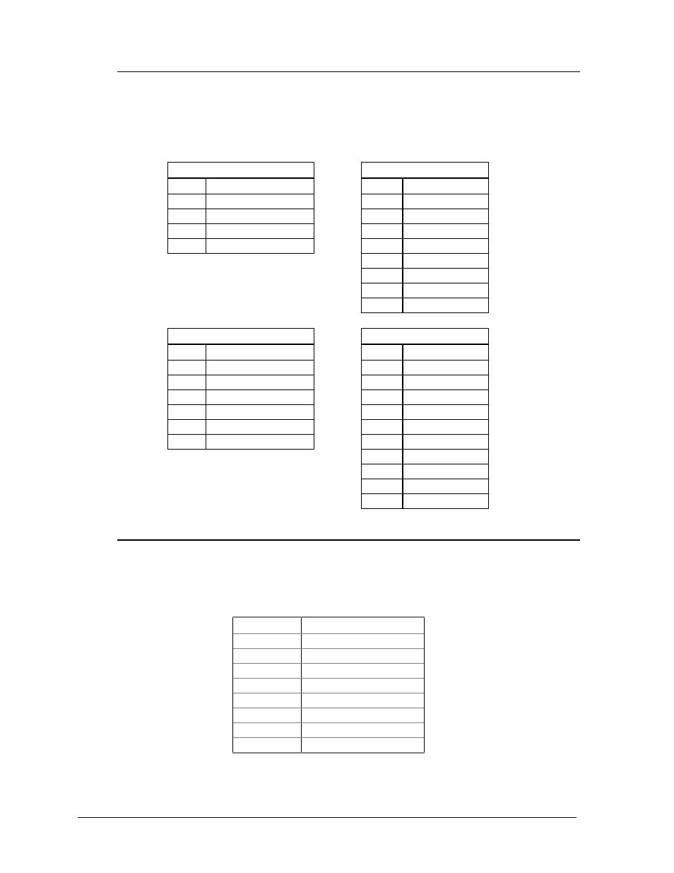
5.2.1 Connectors
The controller receives input from the temperature sensor (TB2) and handset (TB3)
and sends out data to the lamp driver (TB1). Power is brought into the controller on
J1. Refer to Drawing A-37070 for locations of these connectors on the controller.
The following tables show the pin functions of the jack and terminal blocks.
J1
TB1
Pin
Function
Pin
Function
1
Power (10 VAC)
1
Data Out 1+
2
Power (10 VAC)
2
Data Out 1-
3
Reset
3
Data Out 2+
4
Reset Ground
4
Data Out 2-
5
Switch 1+
6
Switch 1-
7
Switch 2+
8
Switch 2-
TB2
TB3
Pin
Function
Pin
Function
1
Photocell
1
RX (Handset)
2
GND
2
TX
3
+5 Volts
3
CTS
4
GND
4
RTS
5
Temp. In
5
GND
6
GND
6
+5 Volts
7
Network +
8
Network -
9
C.L. +
10
C.L. -
5.2.2 Switches
Refer to Drawing A-37070 for the location of the DIP switch package on the
controller. The following table shows the function of each switch. Refer to Section
4.8 for additional switch setting information.
Switch #
Function
1
Lamp Test
2
Alternate Test
3
Real Time Clock
4
12/24 Hour
5
Daylight Savings
6
Indoor Controller
7
8 Column Driver
8
7/8 Segment Mode
- TI-3031 4-Inch LED Bar-Digit Locker Room Clock (22 pages)
- ST-2005 Backlit & Non-Backlit Scorer’s Tables (24 pages)
- BB-2135 Backboard LED Light Strip (36 pages)
- TN-2563 Tuff Sport Indoor Multi-Court Tennis LED Scoreboard (112 pages)
- BB-2144 Tuff Sport Basketball LED Scoreboard (184 pages)
- TN-2607 Single-Court Outdoor LED Tennis Scoreboard (134 pages)
- CR-2004 Multi-Section Cricket Scoreboard (90 pages)
- FT-7150 Touchpad (29 pages)
- SW-2008 Aquatics/Track LED Scoreboard (84 pages)
- SO-1424-11 Multi-Section Outdoor LED Scoreboard (158 pages)
- FB-4005-31 DistaView Outdoor LED Scoreboard (64 pages)
- MS-2018 Generation III Stackable LED Scoreboard (76 pages)
- GM-2103 LED Gymnastics Scoreboards (38 pages)
- HS-200 Horn Start (36 pages)
- Indoor Hockey Goal Lights (44 pages)
- LED End-of-Period Basketball Lighting (34 pages)
- MS-2013 Portable LED Scoreboard (52 pages)
- WR-2106 Matside Jr. LED Wrestling Scoreboard (44 pages)
- TI-2021 Multipurpose Track & Field LED Timing Display (50 pages)
- P1647 Multi-Section Outdoor LED Scoreboard (52 pages)
- P1647 Multi-Section Outdoor LED Scoreboard (50 pages)
- DA-1200 Outdoor Decorative Accent (30 pages)
- 2000 Rodeo OmniSport (72 pages)
- Outdoor LED Scoreboards Installation (58 pages)
- Outdoor LED Scoreboards Service Manual (52 pages)
- SO-2014 Generation IV Multi-Section Outdoor LED Scoreboard (208 pages)
- P1647 Multi-Section Outdoor LED Scoreboard (44 pages)
- PC-2001 Pace Clock System (40 pages)
- PC-2002 Pace Clock System (32 pages)
- BB-314 Portable LED Basketball Scoreboard (28 pages)
- Protective Screen (4 pages)
- TI-2002 Portable LED Timer (32 pages)
- Radar Gun Speed of Pitch Interface (27 pages)
- TI-2026 Segment Timer (28 pages)
- Single-Section Outdoor LED Scoreboards (46 pages)
- LED Aquatics/Track Displays SW-2000 Series 10 Numeric Digit (86 pages)
- TI-2022 Portable LED Timer (32 pages)
- Single Section DistaView Outdoor LED Scoreboards Generation IV (99 pages)
- BB-2151 (NBA only) Transparent Shot Clock (48 pages)
- TN-2563 Tuff Sport Indoor LED Tennis Scoreboard (34 pages)
- Scoreboard Trumpet Horn (50 pages)
- ST-3001 Tuff Sport & ColorSmart LED Scorer’s Table (48 pages)
- Tuff Sport & ColorSmart Indoor LED Scoreboards (46 pages)
- Tuff Sport Indoor LED Scoreboards (40 pages)
- Tuff Sport& ColorSmart FourSided Indoor LED Scoreboards (58 pages)