2 controller diagnostics, Controller diagnostics, Figure 32: controller diagnostic leds – Daktronics Galaxy AF-3400 34 mm Monochrome/RGB User Manual
Page 42: Figure 33: temperature sensor board
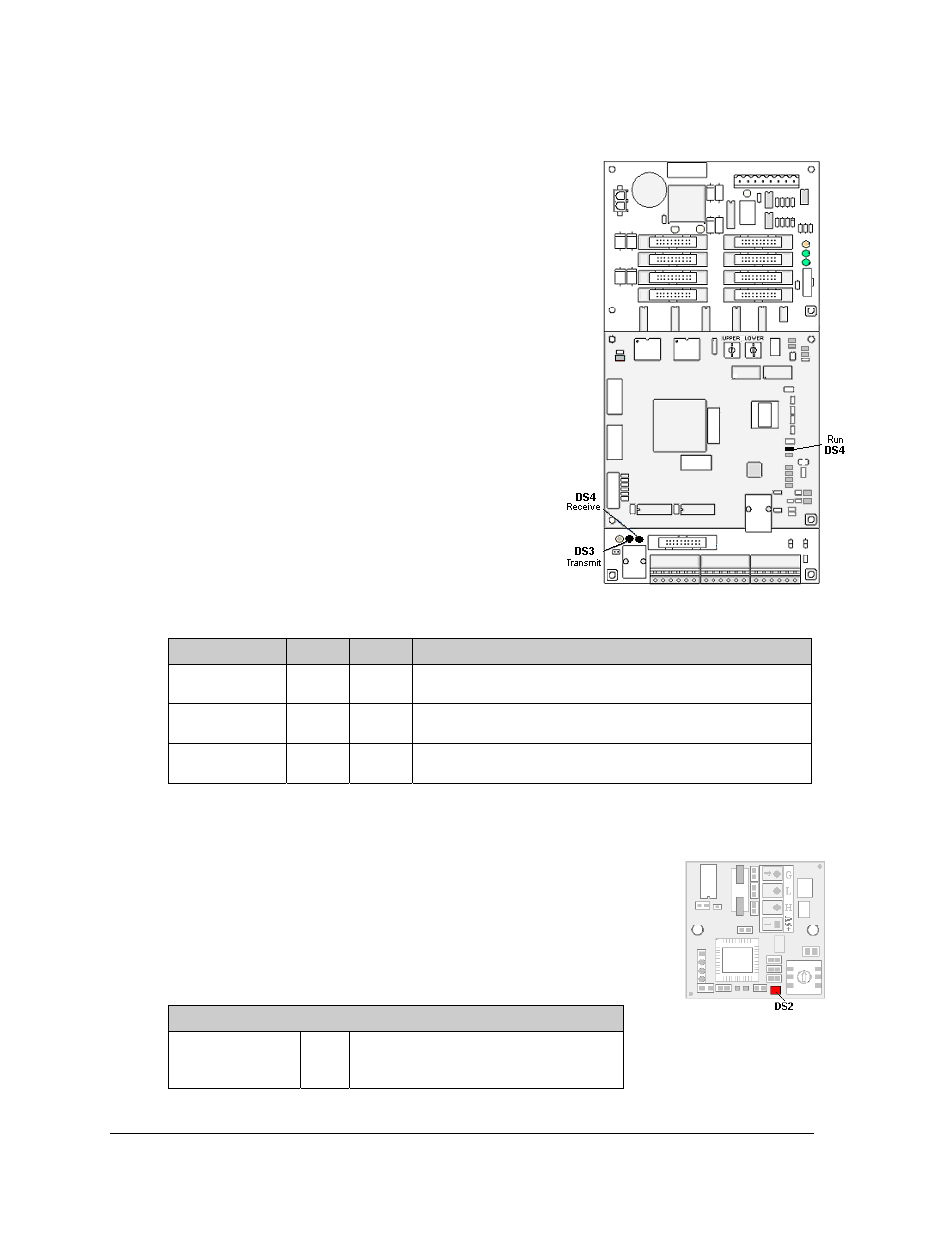
7.2 Controller Diagnostics
The controller is the component that receives
communication from the computer and then sends data
to the modules. Figure 32 illustrates a typical
controller.
Figure 32: Controller Diagnostic LEDs
Diagnostic LEDs are located at various places on the
controller. The following table details some essential
LEDs to monitor and the information that each LED
provides. The LED name and number are noted in
Figure 32.
Note that some LEDs, such as “Run” and “Receive
signal”, have the same number. This occurs because the
controller includes two layers of circuit board which
are not easily shown in an illustration. Be sure to note
the name as well as the number of the LED when
looking at the diagnostics chart.
Figure/ label
LED #
Color
Operation
Run
DS4
Red
Steady FLASH about once per second indicates controller is
working properly.
Send signal
TX1
DS3
Yellow
OFF is the normal state. FLASH when transmitting
communication from the computer.
Receive signal
RX1
DS4
Yellow
OFF is the normal state. FLASH when receiving
communication from the computer.
Temperature Sensor Diagnostic
If the display includes a temperature function, the temperature sensor
board will also provide diagnostic information. The temperature sensor
board is located inside the temperature sensor housing which hangs at
or near the display. Refer to Temperature Sensor Replacement in Section
8.2 for directions on opening the sensor. The sensor board diagram in
Figure 33 shows the red diagnostic LED (DS2) near the bottom edge of
the component.
Figure 33: Temperature
Sensor Board
Temperature Sensor
DS2
Red
Run
FLASH at variable rates when sending
temperature information; evidence that
the unit has power.
Diagnostics and Troubleshooting
34