4 radio communication, Radio communication, Figure 18: radio communication layout – Daktronics Galaxy AF-3400 34 mm Monochrome/RGB User Manual
Page 28
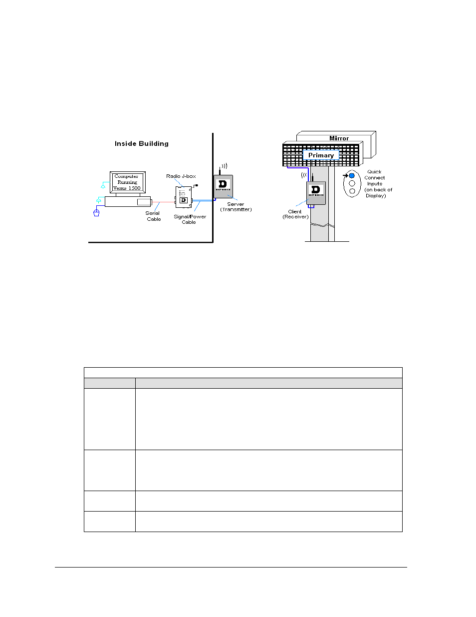
4.4 Radio Communication
If the communication system is Radio, look for:
• a radio J-box near the computer.
• a server radio outside the building and a second (client) radio at the display.
Figure 18: Radio Communication Layout
Connections
• Computer to radio J-box − ten-foot (3m) cable with 9-pin plugs on both ends, one
connecting to computer or USB adaptor and the other plug connecting to radio J-box at
“DB9 Female V1500 PC Connect”.
• Radio J-box 12 VAC power pack plugged into outlet.
• Radio J-box to radio transmitter on building − Phoenix plug on side of J-box to Phoenix
plug inside radio transmitter.
• Server radio to client radio – clear line-of-sight between radios for strong transmission.
• Radio receiver to display − quick-connect cable from receiver to top jack on display back.
Troubleshooting
Component Check:
Cable
Connections:
•
The cable connects the computer to the radio J-box.
•
All the wires are connected at the radio J-box and at the “server” radio; the
wires make good electrical contact with the metal, no interference. .
•
The color sequence of the wires should be the same to both the radio J-box
and the server (e.g. black, white, red and black, white, red).
•
The cable is connected from the radio client to the top jack on back of display.
Diagnostic
LEDs
•
The green LEDs will be on when the radio J-box has power.
•
The amber LED is on when the computer is connected to the radio J-box.
•
The red and amber transmit and receive LEDs will flash when sending and
receiving signal from the display; otherwise they are off.
Display
Power:
•
The display is either running a message or showing a single pixel flashing in
the bottom right corner of the display when power is on.
Software:
•
The software and the display are set for the same network address.
•
Refer to the software manual for other possible conditions.
Signal Installation
20