Optional temperature sensor mounting – Daktronics Galaxy 46 mm Outdoor Series AF-3400 User Manual
Page 88
p. 3 of 6
Optional Temperature Sensor Mounting
ED-14377-Rev 4
3 October 2007
Using the quick-connect cable and less than the 25-foot cable
1. Open the temperature sensor housing by removing the four nuts from the bottom
and then removing the five bottom disks. Refer to Drawing A-198371 for details on
sensor housing disassembly.
2. Disconnect the quick-connect CAN temperature sensor cable from the temperature
terminal block in the CAN temperature sensor housing.
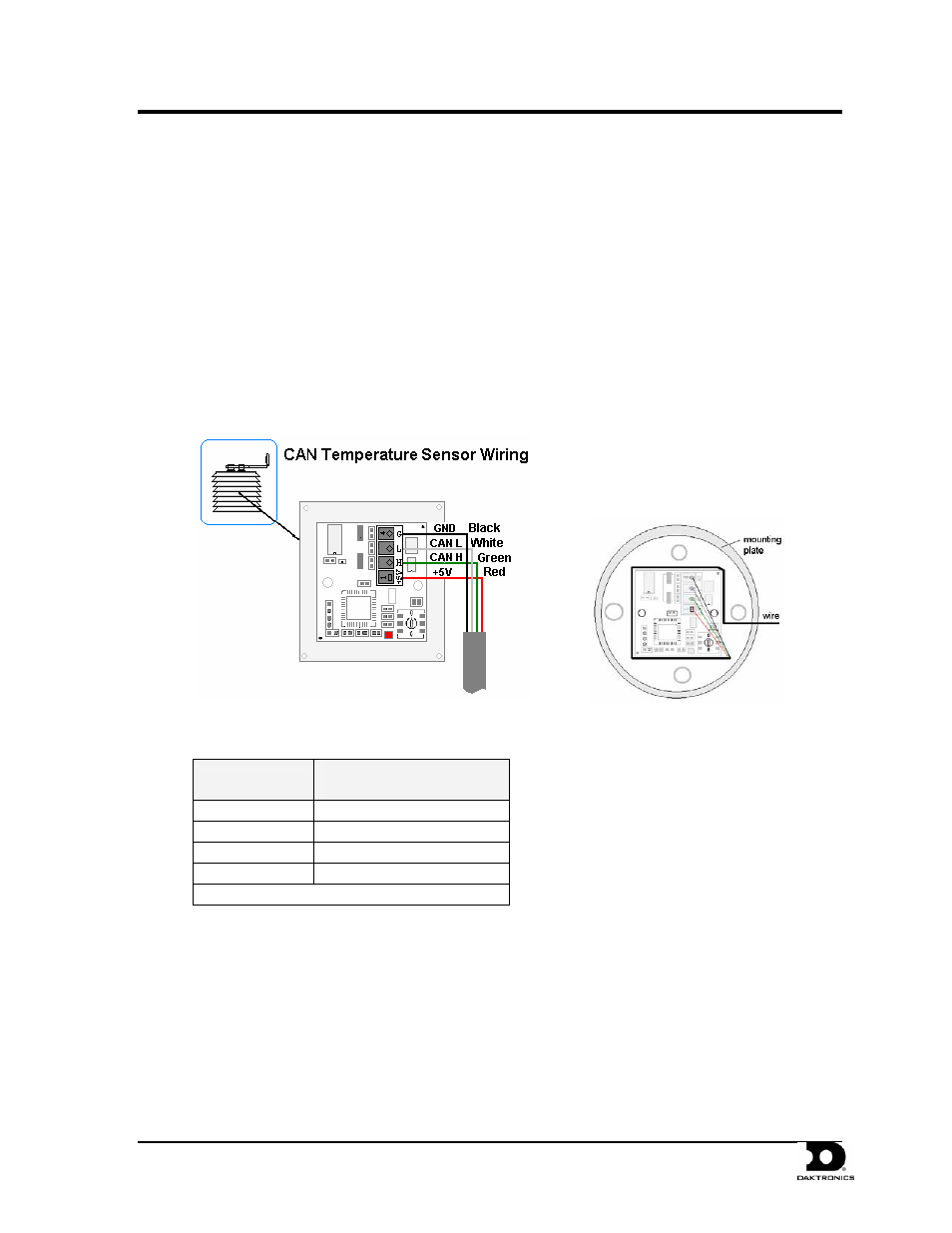
3. Cut the cable to the desired length and reattach to the temperature sensor terminal
block in the CAN temperature sensor housing. Refer to the table and Figure 6 for the
temperature sensor wiring.
4. Make sure to route cable around the sensor board as shown in Figure 7 and Drawing
A-197884.
5. Reconnect the cable and reassemble the sensor.
Figure 6: CAN Temperature Sensor Wiring
Figure 7: Wiring Around Sensor
Wire Color
Temperature Sensor
Terminal Block (TB1)
Red
+5V CAN (Pin 1)
Green
CANH (Pin 2)
White
CANL (Pin 3)
Black
GND (Pin 4)
*Note: Do not terminate shield at this point.