Daktronics Galaxy 46 mm Outdoor Series AF-3400 User Manual
Page 44
Maintenance and Troubleshooting
4-10
Complete the following steps to remove the controller from the display:
• The tools required for this are a 1/8" hex wrench and a 3/16" nut driver.
1. Turn off power to the display.
2. Remove the module directly in front of the controller in the lower left
corner of the primary display.
3. Disconnect power plug from J5.
4. Remove all power and signal connections from the board (pushing apart the
latches and carefully pulling them from the jack will release the “Locked”
connectors). When replacing the board, it is helpful to have the cables
labeled as to which was removed from which connector.
5. Remove the six screws holding the board in place using a 3/16" nut driver.
6. Take note of the address of the controller, and ensure the address on the
replacement board is the same.
Follow the previous steps in reverse order to install a new controller board.
The rotary switches set the hardware address, which the software uses to identify that
particular display. When replacing a controller board, be sure to set the rotary
switches in the same address configuration as the defective controller. Each
controller in a network needs a unique address.
Note: Setting both rotary switches to address 0 (set the switches to 0 by rotating
them counterclockwise until the arrow points to 0) can activate a test mode. The
display’s power must be turned off and then turned back on to activate the test mode.
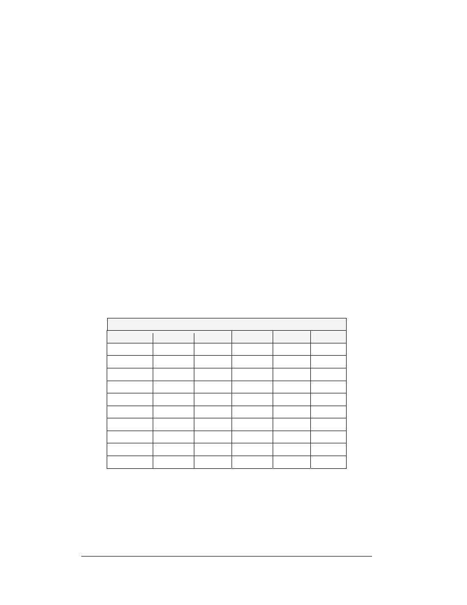
Controller Address Settings
Address
Upper
Lower
Address
Upper
Lower
Test Mode
0 0 10
0 A
1
0 1 11
0 B
2
0 2 12
0 C
3
0 3 13
0 D
4
0 4 14
0 E
5
0 5 15
0 F
6
0 6 16
1 0
7
0 7 17
1 1
8
0 8 …
… …
9
0 9
240
F 0