Component identification, Component identification -5, Figure 2: version 3 controller -5 – Daktronics Galaxy 46 mm Outdoor Series AF-3400 User Manual
Page 15: 4 component identification
1.4 Component Identification
The following illustrations depict some of the more commonly accessed Galaxy
®
display components. Because Daktronics occasionally alters standard design to meet
customer needs, the actual display design may vary slightly from the illustrations
below.
This is only a brief overview. Refer to Section 4 for additional information on
maintaining the various display components. Additional definitions are given in the
communication manual provided with your display.
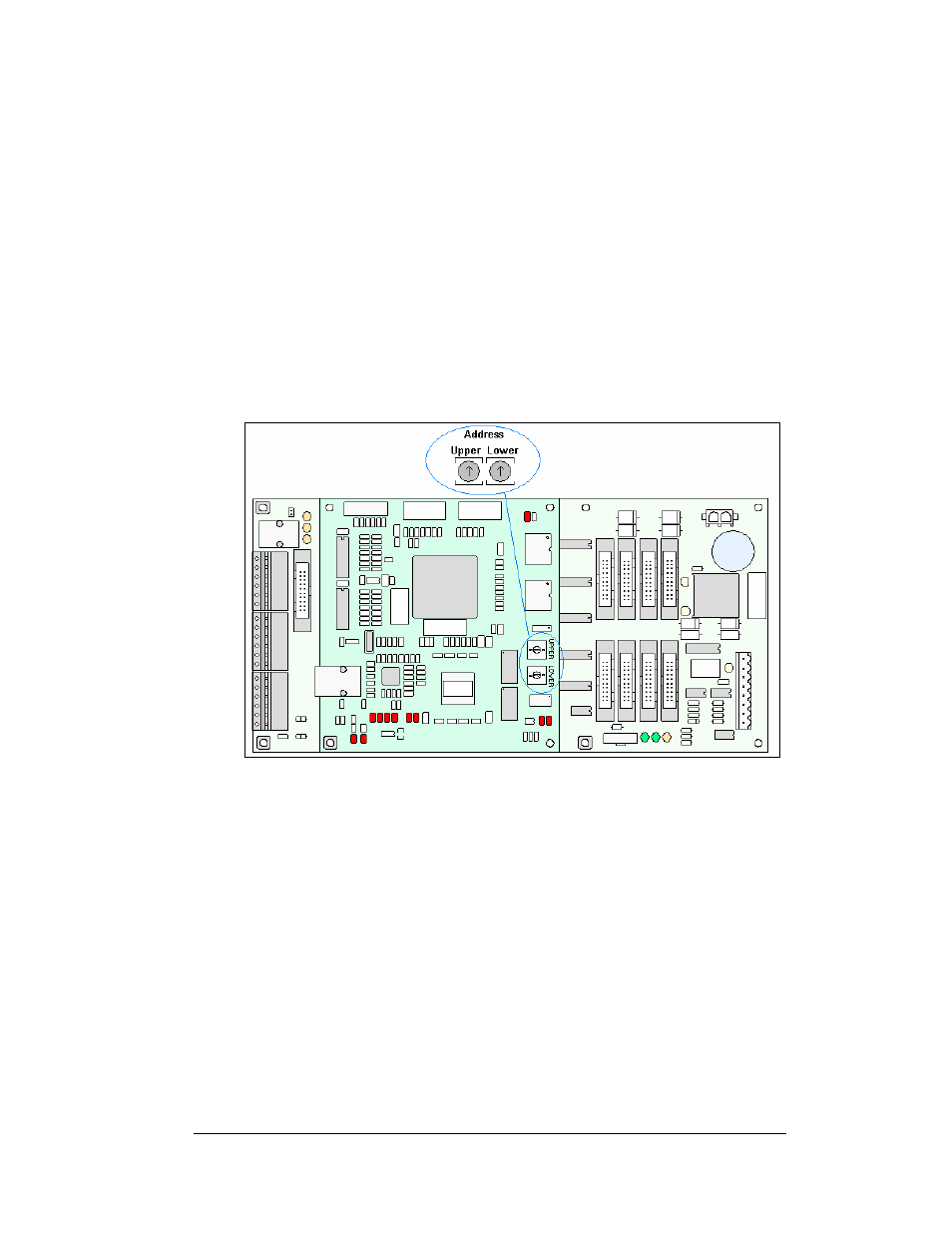
Controller: The display’s controller is the “brains” of the display (refer to Figure
2). The controller receives, translates and activates the signal information from the
computer to the appropriate pixels on the display.
Figure 2: Version 3 Controller
Display Address: The display address is an identification number assigned to each
display of a network. Rotating the address switches on the controller sets the display
address. The control software uses the address to locate and communicate with each
display. Displays that are on the same network cannot have the same address.
Driver/Pixel Board: The LED pixels are mounted directly onto the driver/pixel
board. This board is also responsible for the switching and intensity levels of the
LEDs. The driver/pixel board is also called a module.
Galaxy
®
: Daktronics trademarked name for LED monochrome, tri-colored or RGB
matrix displays.
LED (light emitting diode): This is a low energy and high intensity lighting unit.
Louver: Black plastic shade positioned horizontally above each pixel row. The
louvers increase the level of contrast on the display face and direct LED light.
Introduction
1-5