Service and diagnostics, Service and diagnostics -7, 5 service and diagnostics – Daktronics Galaxy 46 mm Outdoor Series AF-3400 User Manual
Page 41
Maintenance and Troubleshooting
4-7
4.5 Service
and
Diagnostics
Reference Drawings:
Schematics............................................................... Refer to Appendix A
The following sub-sections address servicing of the following display components:
•
Transformer, RFI filter
•
Controller
•
Power supplies
The sub-sections also address any diagnostic LEDs, fuses, and signal/power
connectors found on the unit. On the Schematics the components are denoted as
follows:
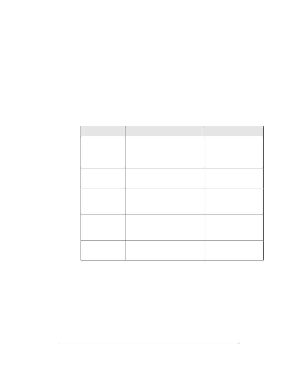
Component…
Denoted As…
Location…
Filter and/or
Transformer
0A-1327-0100 (120V, 1 circuit)
0A-1327-0101 (120/240V, 2 circuit)
0A-1327-0104 (120/240V, 4 circuit)
0A-1327-0105 (120/240V, 6 circuit)
0A-1327-0109 (120/240V, 8 circuit)
Inside the power termination
box
Controller
0A-1229-0013
Usually behind the bottom
left module of the bottom
section.
Modules Squares
0A-1342-4550 (RGB)
0A-1342-4000 R
0A-1342-4002 A
Over entire face of the
display A101 through A309
(includes driver)
RGB Power
Supplies
0A-1327-0013 1000W @ 1
13.1 VDC
0A-1327-0015 600W @ 1
13.1VDC
Behind modules (refer to
your display’s Schematic)
Light Detector
0A-1327-3000
0A-1327-3003
0A-1327-3004
Behind\above the top left
module